Radial capillary seal for fluid dynamic bearing motors

a technology of fluid dynamic bearings and capillaries, which is applied in the direction of sliding contact bearings, instruments, record information storage, etc., can solve the problems of limiting the density of data tracks and the overall performance of the disc drive system, the misalignment of data tracks and the read/write transducer, and the disc drive system's performance. achieve the effect of easy assembly

Inactive Publication Date: 2005-12-29
SEAGATE TECH HDD HLDG +3
View PDF6 Cites 13 Cited by
  • Summary
  • Abstract
  • Description
  • Claims
  • Application Information

AI Technical Summary

Benefits of technology

[0021] It can further be seen that the design will be relatively easy to assemble, and supports an easy filling sequence of oil into the reservoir in the fluid bearing gap.

Problems solved by technology

First is the problem of vibration generated by the balls rolling on the bearing raceways.
This vibration results in misalignment between the data tracks and the read / write transducer.
This source of vibration limits the data track density and the overall performance of the disc drive system.
Vibration results in misalignment between the data tracks and the read / write transducer.
Vibration limits therefore the data track density and the overall performance of the disc drive system.
Further, mechanical bearings are not always scalable to smaller dimensions.
This is a significant drawback, since the tendency in the disc drive industry has been to continually shrink the physical dimensions of the disc drive unit.
However, the fluid may in many instances be jarred out of the bearing gap by shock or vibrations; further, variations in operating an environmentals temperatures may cause some evaporation of the fluid over the long term.
However, the two functions, providing a seal and providing a reservoir are somewhat conflicting.
A large reservoir requires a wide capillary seal gap; but the wider the gap, the lower the oil retention capability.

Method used


Image

  • Radial capillary seal for fluid dynamic bearing motors
  • Radial capillary seal for fluid dynamic bearing motors
  • Radial capillary seal for fluid dynamic bearing motors

Examples


Embodiment Construction

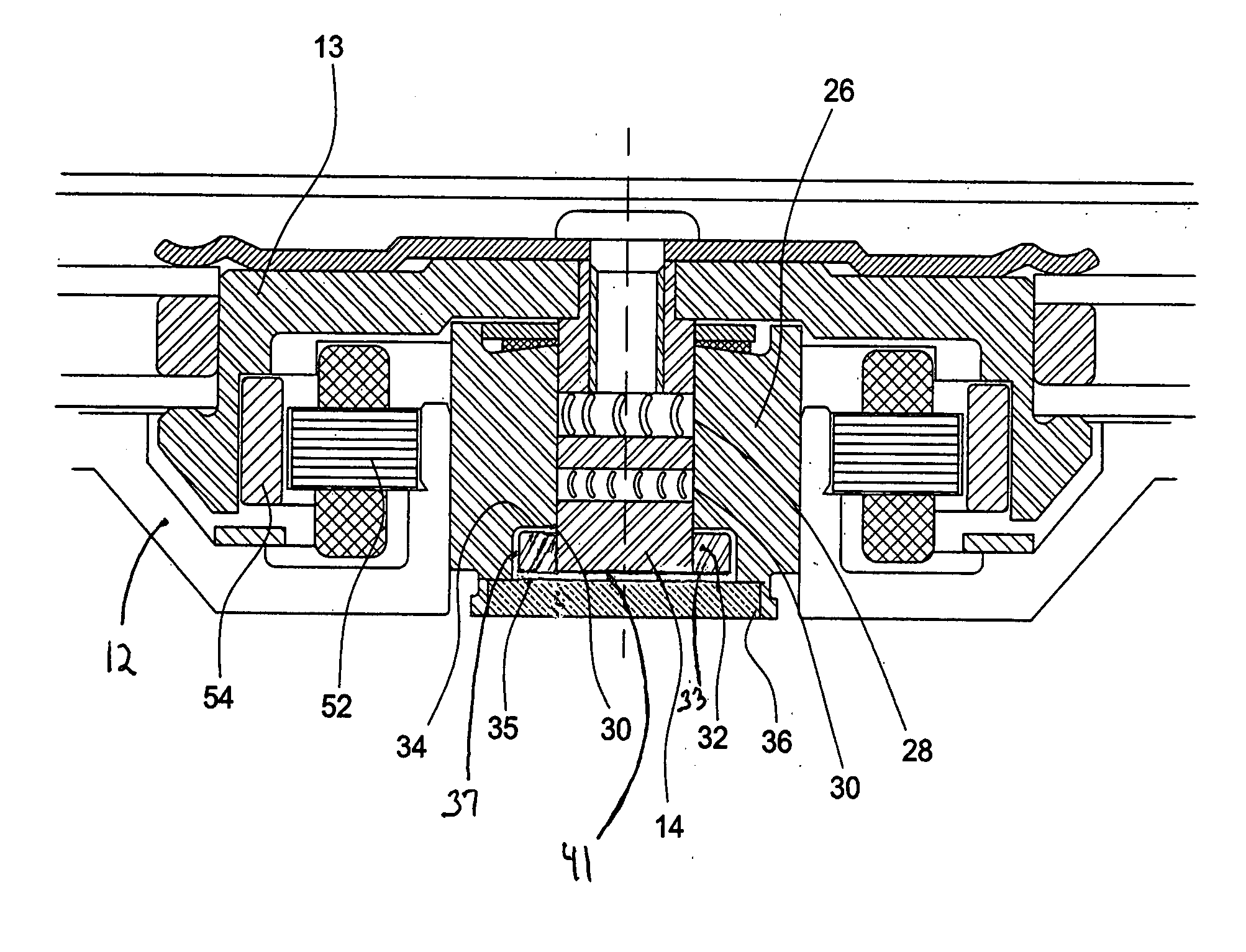
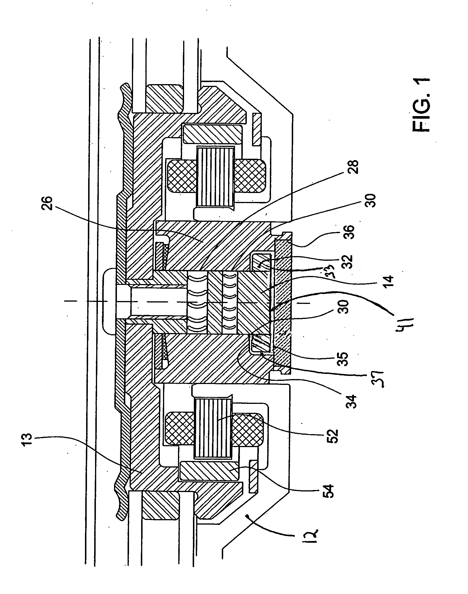
[0030] Reference will now be made in detail to exemplary embodiments of the invention, examples of which are illustrated in the accompanying drawings. While the invention will be described in conjunction with these embodiments, it is to be understood that the described embodiments are not intended to limit the invention solely and specifically to only those embodiments, or to use solely in the disc drive which is illustrated. On the contrary, the invention is intended to cover alternatives, modifications and equivalents which may be included within the spirit and scope of the invention as defined by the attached claims. Further, both hard disc drives, in which the present invention is especially useful, and spindle motors, where the invention is also especially useful are both well known to those of skill in this field. In order to avoid confusion while enabling those skilled in the art to practice the claimed invention, this specification omits such details with respect to known it...


PUM

PropertyMeasurementUnit
radial widthaaaaaaaaaa
volumeaaaaaaaaaa
volumeaaaaaaaaaa

Abstract

A seal with a primary axis lying in the radial direction so that the fluid bearing is primarily extending in the axial direction between the rotating shaft and surrounding sleeve is disclosed. The capillary seal is positioned with an opening adjacent an end of the fluid bearing gap, and comprises two walls which diverge as they extend radially away from the fluid bearing so that the fluid held in the radial capillary seal is maintained adjacent an end of the gap, while the size of the reservoir defined by the diverging walls provides a large reservoir volume. The seal uses an additional capillary defined by a narrow annulus between the rotating shaft and a seal wall end. The narrow annulus establishes very high shock resistance preventing fluid loss past the outer axial wall of the radially capillary seal, and defines a small surface area from which evaporation can occur.

Description

CROSS REFERENCE TO A RELATED APPLICATION [0001] This application claims priority to provisional application Ser. No. 60 / 370,718, filed Apr. 5, 2002, entitled Radial Capillary Seal for FDB Motors, invented by Alan L. Grantz, et al; that provisional application is incorporated herein by reference.FIELD OF THE INVENTION [0002] The present invention relates to fluid dynamic bearing seals and more particularly to a low profile seal design for use with such a bearing. BACKGROUND OF THE INVENTION [0003] Disc drive memory systems have been used in computers for many years for storage of digital information. Information is recorded on concentric tracks of a magnetic disc medium, the actual information being stored in the forward magnetic transitions within the medium. The discs themselves are rotatably mounted on a spindle, while the information is accessed by read / write heads generally located on a pivoting arm which moves radially over the surface of the rotating disc. The read / write heads...

Claims


Application Information

Patent Timeline
Patent Type & Authority Applications(United States)
IPC IPC(8): F16C33/74G11B19/20
CPCF16C17/105F16C17/107F16C2370/12G11B19/2009F16C33/745
Inventor GRANTZ, ALAN L.KHAN, RAQUIB U.PARSONEAULT, NORBERT STEVEN
Owner SEAGATE TECH HDD HLDG
Why Eureka
Try Eureka