Methods and apparatus for assembling a bearing assembly

a technology of bearing assembly and assembly method, which is applied in the direction of mechanical equipment, machines/engines, instruments, etc., can solve the problems of affecting the operation of the engine, and/or the engine being removed unscheduled, and the chip detection system and sem analysis system can only detect the spalling of the bearing, and the known vibration measurement system may not be able to successfully identify the bearing failur

Inactive Publication Date: 2005-12-29
GENERAL ELECTRIC CO
View PDF7 Cites 29 Cited by
  • Summary
  • Abstract
  • Description
  • Claims
  • Application Information

AI Technical Summary

Benefits of technology

[0006] In one aspect method for predicting bearing failure, wherein the bearing includes an inner race, an outer race, and a plurality of rolling elements between the inner and outer race is provided. The method includes coupling a sensor assembly to the outer race, the sensor assembly including at least one temperature sensor and at least one acoustic sensor, generating a bearing performance model based on an initial signal received from the sensor assembly, receiving a second signal from the sensor assembly, and comparing the second signal to the bearing performance model to predict a bearing failure.

Problems solved by technology

During operation, failure of a bearing assembly may result in an In Flight Shut Down (IFSD), and / or an Unscheduled Engine Removal (UER).
However, known magnetic chip detection systems and SEM analysis systems can only detect a bearing spalling that has already occurred.
However, known vibration measurement systems may not be able to successfully identify the bearing failure if the transmitted signal is degraded when passed through a lubricant film that is used to lubricate the bearing.
Accordingly, identifying the bearing component frequencies among a plurality of engine operating frequencies may be relatively difficult.
Accordingly, known systems are generally not effective in detecting initial bearing flaws and / or defects that may result in bearing spalling, in monitoring bearing damage and / or spall propagation, or in assessing the overall bearing damage including multi-spall initiations and progression.

Method used


Image

  • Methods and apparatus for assembling a bearing assembly
  • Methods and apparatus for assembling a bearing assembly
  • Methods and apparatus for assembling a bearing assembly

Examples


Embodiment Construction

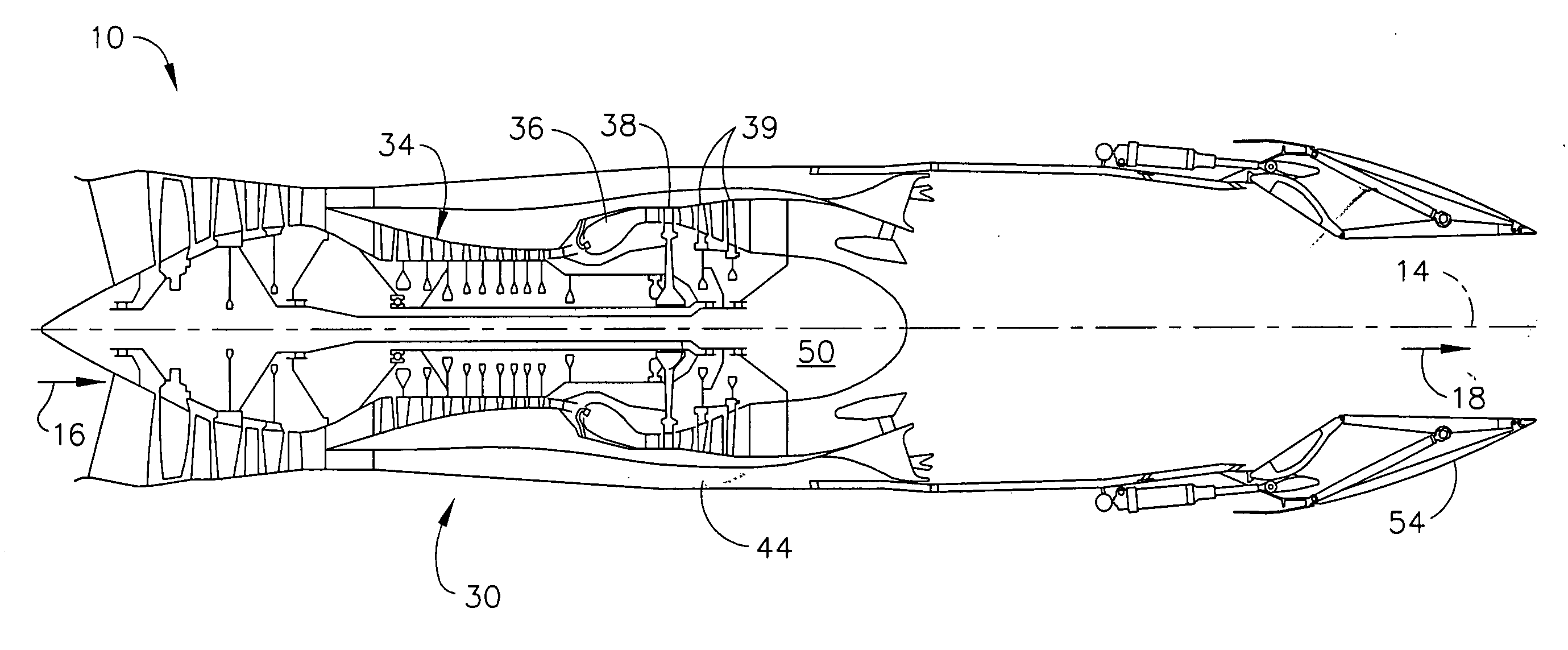
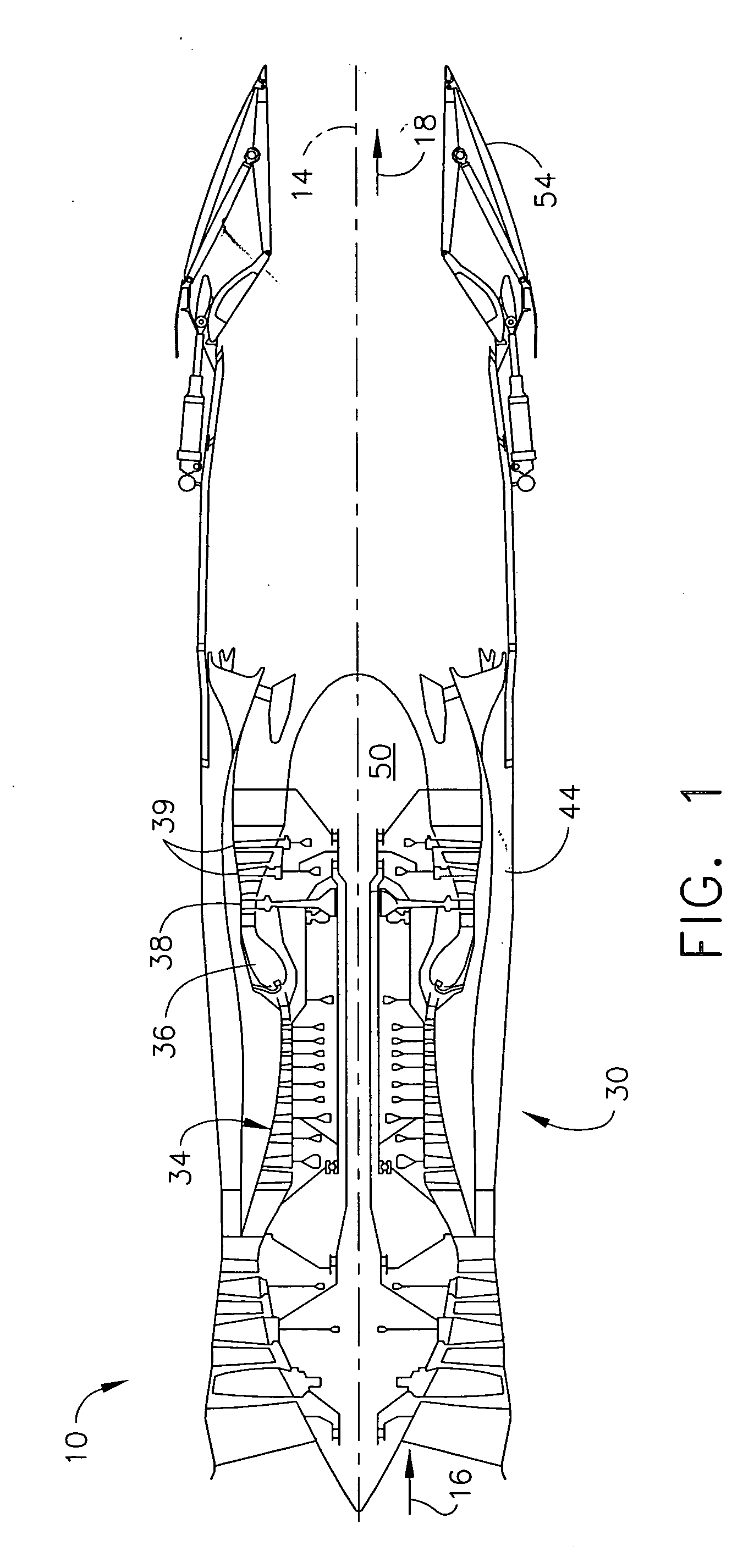
[0016]FIG. 1 is a cross-sectional side view of an exemplary gas turbine engine 10. In one embodiment, engine 10 is an F110 engine available from General Electric Aircraft Engines, Cincinnati, Ohio. Engine 10 has a generally longitudinally extending axis or centerline 14 extending in a forward direction 16 and an aft direction 18. Engine 10 includes a core engine 30 which includes a high pressure compressor 34, a combustor 36, a high pressure turbine 38, and a power turbine or a low pressure turbine 39 all arranged in a serial, axial flow relationship. In an alternative embodiment, core engine 30 includes a compressor, a detonation chamber, and a turbine arranged in a serial, axial flow relationship. Engine 10 also includes a bypass duct 44 that surrounds core engine 30, and enables fluid flow to be routed downstream from core engine 30 rather than through core engine 30. In an alternative embodiment, engine 10 includes a core fan assembly (not shown). An annular centerbody 50 extend...


PUM


Abstract

A method for predicting bearing failure, wherein the bearing includes an inner race, an outer race, and a plurality of rolling elements between the inner and outer race. The method includes coupling a sensor assembly to the outer race, the sensor assembly including at least one temperature sensor and at least one acoustic sensor, generating a bearing performance model based on an initial signal received from the sensor assembly, receiving a second signal from the sensor assembly, and comparing the second signal to the bearing performance model to predict a bearing failure.

Description

STATEMENT REGARDING FEDERALLY SPONSORED RESEARCH OR DEVELOPMENT [0001] The U.S. Government may have certain rights in this invention pursuant to contract number HR001-04-C-0002.BACKGROUND OF THE INVENTION [0002] This application relates generally to gas turbine engine rotor assemblies, and more particularly, to bearing assemblies used with gas turbine engine rotor assemblies. [0003] Gas turbine engines typically include a fan rotor assembly, a compressor, and a turbine. The turbine includes an array of rotor blades extending radially outward from rotor disk that is coupled to a rotor shaft. The rotor shaft transfers power and rotary motion from the turbine to the compressor, and is supported longitudinally through a plurality of roller bearing assemblies and axially through at least one thrust bearing assembly. Known roller bearing assemblies include rolling elements supported within a paired race. [0004] During operation, failure of a bearing assembly may result in an In Flight Shu...

Claims


Application Information

Patent Timeline
Patent Type & Authority Applications(United States)
IPC IPC(8): G01M13/045F01D17/02F01D21/00F01D21/04F01D21/14F01D25/16F02C7/06F16C19/52F16C32/00F16C33/58F16C41/00F16C41/04G01H1/00
CPCF01D17/02F01D21/003F01D21/14F16C2360/23F16C33/58F05D2270/09F05D2270/305F16C19/52F16C33/586F16C2233/00
Inventor SINGH, ANANT PALSEXTON, LARRY JAY
Owner GENERAL ELECTRIC CO
Why Eureka
Try Eureka