

Optical connector cleaning tool, cleaning tape, optical connector cleaning method, optical component cleaning tool, and optical component cleaning tool
a technology for cleaning tools and connectors, applied in cleaning processes and apparatus, instruments, chemistry apparatuses and processes, etc., to achieve the effect of reliably removing contaminants on the connection end fa
- Summary
- Abstract
- Description
- Claims
- Application Information
AI Technical Summary
Benefits of technology
Problems solved by technology
Method used
Image

Examples
first embodiment
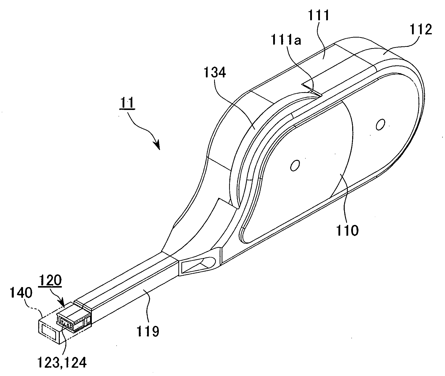
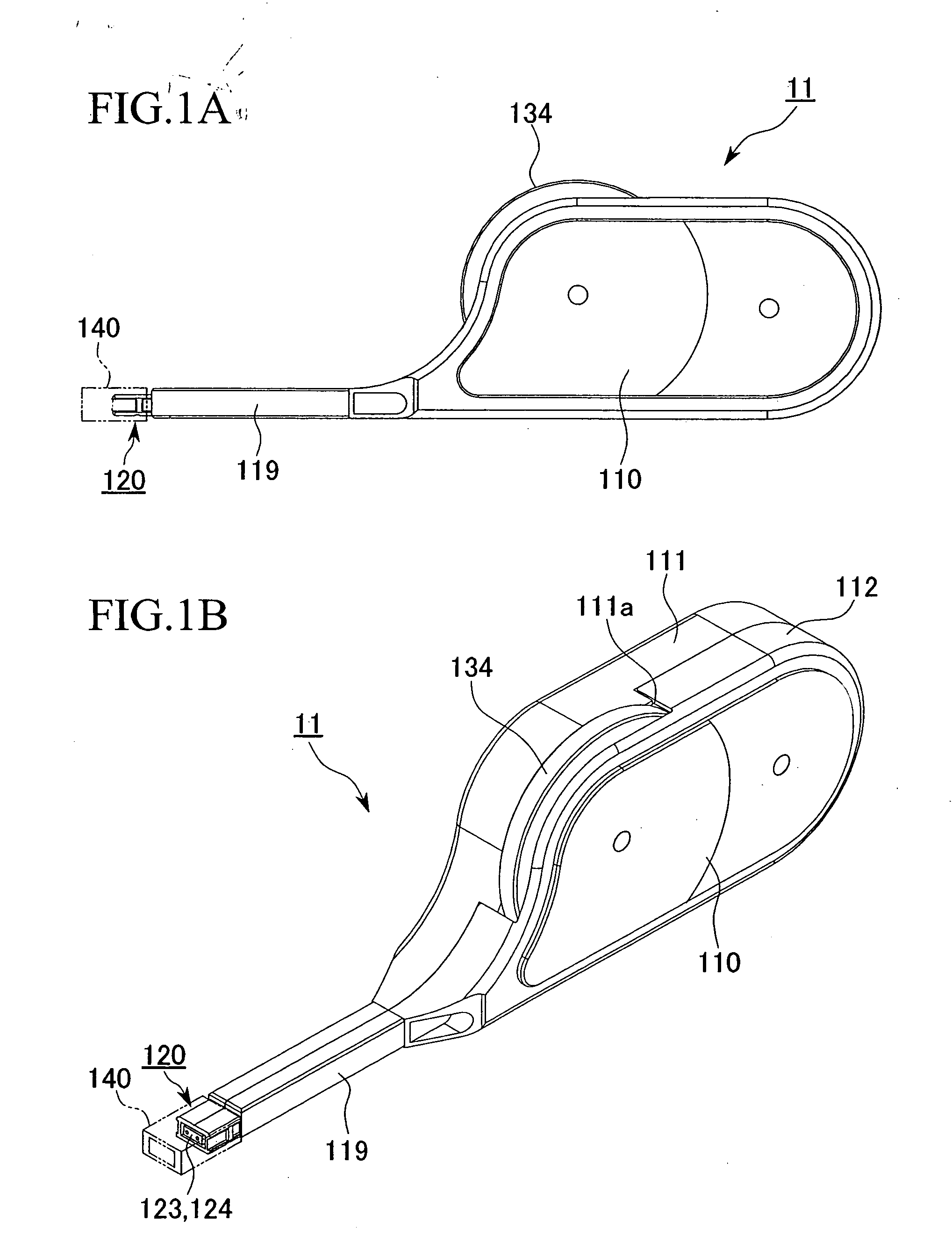
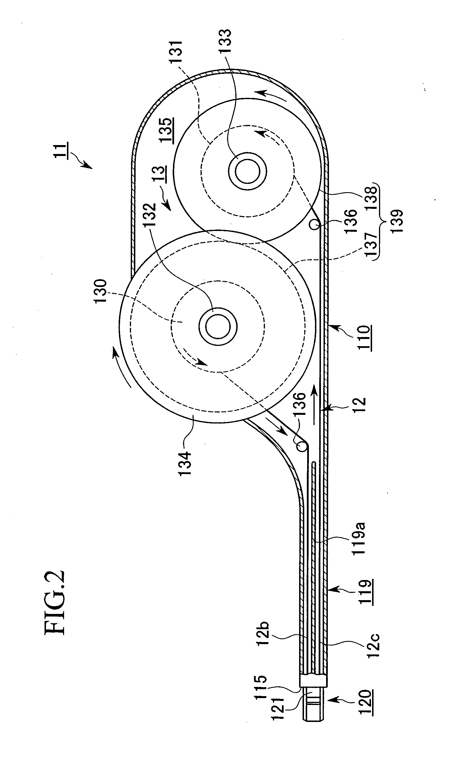
[0176]FIGS. 1A through 6 are views showing the optical connector cleaning tool of the present invention (hereafter simply referred to as the “cleaning tool”). FIGS. 7 through 10 are views showing an embodiment of an optical connector cleaning method using the cleaning tool.
[0177] As will hereinafter be described in detail, a cleaning tool 16 of the present embodiment is equipped with a cleaning unit 11 that integrates a tool body 110 and an insertion portion 120 and has a built-in driving mechanism 13, a connector cleaning guide 140 (an optical connector cleaning guide. Hereafter simply referred to as a guide 140) formed to be mountable on the insertion portion 120 of the cleaning unit 11, and a cap 150 that can be detachably attached to a plug insertion hole (described hereinafter) of the guide 140.
[0178] As shown in FIGS. 5, 9 and 10, optical connectors 160, 180 and connector housing 170 to which the cleaning tool 16 of the first embodiment is applied are Multifiber Push-On (MPO)...
third embodiment
[0243]FIGS. 12A through 14 are views showing the optical connector cleaning tool of the present invention.
[0244] In FIGS. 12 through 14, those reference numerals that are the same as the reference numerals used in FIGS. 1A through 11 indicate identical or similar constitutions as in the optical connector cleaning tool of the aforementioned first embodiment, and duplicate explanations will be omitted herein.
[0245] As shown in FIG. 14, the insertion portion 120 of the cleaning unit 11 used in the optical connector cleaning tool 16 of the third embodiment is provided with a key 120c in a protruding manner to fit a key groove 172a on the optical adaptor 170, thereby blocking reverse insertion in the optical adaptor 170.
[0246] As shown in FIGS. 12A through 12D and FIG. 13, the guide 140 has the guide body 140b formed in an approximately sleeve shape (tube shape) from plastic and the lid 153 connected to one end of the guide body 140b by the hinge 154. A fitting hole 153b that fits a pr...
fourth embodiment
[0264]FIGS. 15A through 25 are views showing the optical connector cleaning tool of the present invention (hereafter simply referred to as the “cleaning tool”).
[0265]FIG. 20 is a perspective view corresponding to the state shown in FIG. 18, and FIG. 21 is a perspective view corresponding to the state shown in FIG. 19.
[0266] An optical connector plug 260 (sometimes referred to hereafter simply as an optical plug) and an optical connector adaptor 270 (connector housing. Sometimes referred to hereafter simply as an optical adaptor) to which a cleaning tool 21 of the fourth embodiment is applied are as shown in FIGS. 24 and 25 Multifiber Push-On (MPO) type optical connectors defined according to JIS C 5982.
[0267] The optical plug 260 is an optical connector plug of a constitution housing a Mechanically Transferable (MT) type optical connector ferrule 261 (hereafter simply referred to as a ferrule) defined according to JIS C 5981 at a distal end portion of a plastic sleeve-shaped housi...
PUM
 Abstract
Description
Claims
Application Information