Compact Heat Pump Using Water as Refrigerant

a heat pump and water technology, applied in the field of vacuum heat pumps, can solve the problems of low overall heat transfer efficiency, and achieve the effect of reducing the number of droplets, and reducing the cost of operation

Inactive Publication Date: 2009-04-23
IDE TECHNOLOGIES
View PDF6 Cites 27 Cited by
  • Summary
  • Abstract
  • Description
  • Claims
  • Application Information

AI Technical Summary

Benefits of technology

[0017]The intake conduit may be of any appropriate design. For example, it may be advantageous for the intake conduit to have a wide end merging with the circumference of the evaporator, a narrow end adjacent to said compressor, and a straight narrow portion therebetween. Such a design may allow flow stabilization of the vapor entering the compressor. The intake conduit's wide end may be fitted with one or more demisters which are adapted for preventing droplet carryover into the compressor by filtering out water droplets that are over a certain size. This size is normally determined by the anticipated damage that might be inflicted upon the compressor should the droplets impact its blades. The demister may be of the louver type, woven mesh type or the like and may be connected to a heating mechanism for higher efficiency. External surface of the intake conduit facing the condenser may be shaped to form with the casing said sump storage space.
[0018]According to one embodiment of the invention, the heat pump may be designed for use in a vertical orientation such that the second end section is located above the intermediate and first end sections, the latter serving as a pool for the refrigerant. In this case, droplet carryover to the compressor may be largely prevented since most of the droplets are pulled back into the evaporator simply by gravity, allowing optional elimination of the demister. Furthermore, such an orientation allows the provision of a uniform vapor flow into the compressor through the intake conduit, raising the efficiency of the compressor. This advantage may be further emphasized if the heat pump is designed to have an axial symmetry around a vertical axis extending between the first and second ends.

Problems solved by technology

Furthermore, when the product is in the form of ice slurry, the absence of intermediate heat transfer surfaces between the refrigerant and the product prevents the freezing of water on such surfaces, which would normally lower the efficiency of the overall heat transfer.

Method used


Image

  • Compact Heat Pump Using Water as Refrigerant
  • Compact Heat Pump Using Water as Refrigerant
  • Compact Heat Pump Using Water as Refrigerant

Examples


Embodiment Construction

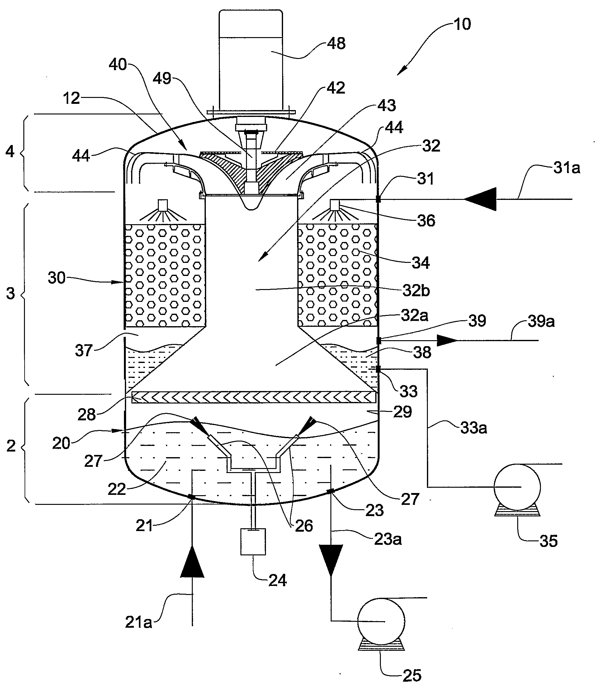
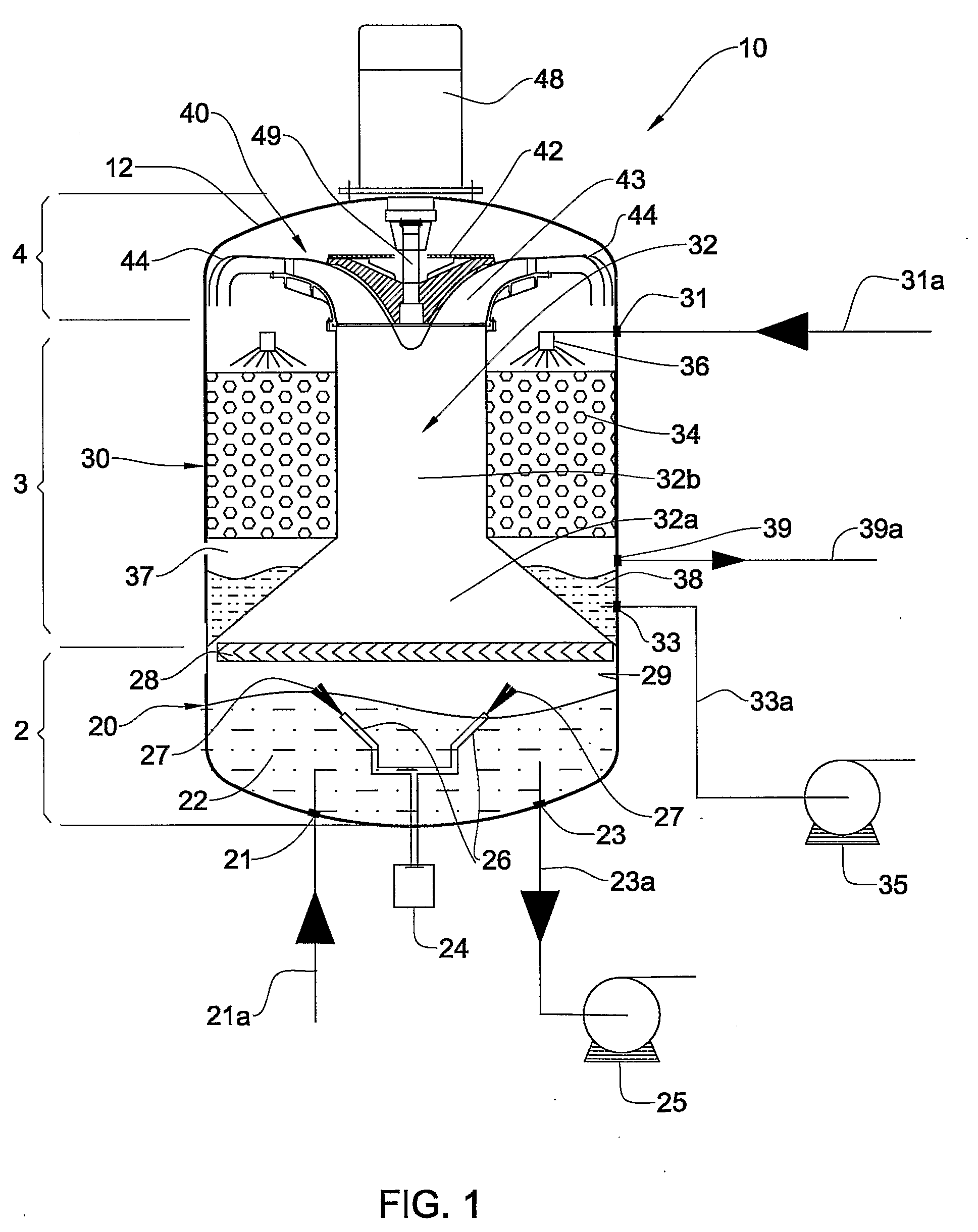
[0032]Attention is first drawn to FIG. 1, where there is shown a schematic cross-sectional view of a vertically positioned heat pump (10), adapted for production of ice slurry. The heat pump comprises a casing (12) with a lower end section (2), an upper end section (4) and an intermediate section (3).

[0033]The evaporator (20) is located at the bottom end section (2) and is in the form of a cavity adapted to accommodate a certain amount of water (22), having a water inlet (21) and an ice slurry outlet (23). The evaporator further comprises a set of scoops for agitation (26) adapted to be powered by a motor (24) located outside the casing (12), and an optional demister (28) located above the water (22) level adapted for filtering water droplets over a certain size from the water vapor passing therethrough.

[0034]The upper end section (4) houses a compressor (40) having a rotor (42), and compressor blades (43) mounted on a main shaft (49) adapted to be powered by a motor (48) located ou...


PUM


Abstract

According to the present invention there is provided a compact heat pump using water as refrigerant, comprising an evaporator (20) located at a first end section of the heat pump casing (12), adapted to allow evaporation of water therefrom, One or more compressors (40) located at a second end section of the heat pump casing adapted to induce said evaporation by maintaining vacuum, provided with an intake conduit (32) extending from the evaporator (20) to the compressor (40) leading vapor thereto. A condenser (30) is located in the intermediate section of the casing (12) wherein the intake conduit (32) passes therethrough, adapted for condensing the vapor. The heat pump also comprises vacuum means (39) allowing creating and maintaining vacuum in the casing. There is also provided a snow dome allowing skiing and snow related activities in above zero conditions using the heat pump for creation of snow or ice slurry.

Description

FIELD OF THE INVENTION[0001]This invention relates to vacuum heat pumps, in particular those that use water as refrigerant.BACKGROUND OF THE INVENTION[0002]A heat pump is a mechanism designed to displace a certain amount of heat energy from a low temperature environment to a high temperature environment by applying work to the refrigerant.[0003]A heat pump may work in an open or closed cycle. In a closed cycle, the pump's functional components form a closed loop through which the refrigerant is cycled over and over again, and in the course of which heat is taken away or given to the refrigerant, respectively heating or cooling the environment outside the heat pump. In open cycle heat pumps, the components are normally arranged along a line for the refrigerant to be driven through the components until it exits the system all together, thereby removing heat from the refrigerant at one end of the line and releasing it at the other end. This kind of cycle requires a constant feed of new...

Claims


Application Information

Patent Timeline
Patent Type & Authority Applications(United States)
IPC IPC(8): F25C5/00F25D23/00F25C3/04F25B1/00
CPCF25C1/16F25B30/00Y02P60/85
Inventor OPHIR, AVRAHAMROJANSKIY, HENRIKHSILUK, RAFIKANIEVSKI, ARIEKANIEVSKI, LARISA
Owner IDE TECHNOLOGIES
Why Eureka
Try Eureka