Hybrid coiled tubing/fluid pumping unit

a technology of coiled tubing and fluid pumping, which is applied in the direction of fluid removal, cleaning apparatus, insulation, etc., can solve the problems of real risk of explosion, sever corrosion, and the equipment needed to compress and pump it adds substantially to the weight of a coiled tubing rig, so as to reduce the onsite footprint and save the environment

Inactive Publication Date: 2007-04-24
LEADER ENERGY SERVICES
View PDF5 Cites 28 Cited by
  • Summary
  • Abstract
  • Description
  • Claims
  • Application Information

AI Technical Summary

Benefits of technology

[0013]The outer end of the coiled tubing can be permanently connected to the nitrogen rig, thus eliminating the need to connect tubing which could potentially be a weak spot in a high pressure line. The permanent connection also limits the amount of high pressure tubing exposed at the work site, making for a safer environment. Because the heater used to vaporize the liquid nitrogen is non-fired, it can be deployed on the hybrid unit immediately adjacent the well bore, which greatly reduces the onsite footprint.

Problems solved by technology

This creates a real risk of explosion and the oxygen's reactiveness can cause sever corrosion by the oxidation of metallic surfaces.
Another disadvantage to the use of air is that the equipment needed to compress and pump it adds substantially to the weight of a coiled tubing rig.
A major issue with coiled tubing units is the amount of coil they can carry without exceeding load limits on both the trailer and public roadways.
This is not sufficient in itself to blow sand from deeper wells.
This limits deeper well applications.
Most obviously, operating costs for two rigs are high because of the extra personnel, fuel and equipment required.
There is the added pollution and cost resulting from the use of two tractor units and an open flame heater.
The high pressure tubing delivering the nitrogen gas to the coiled tubing unit is a hazard and setup and breakdown times before and after the job are increased.

Method used


Image

  • Hybrid coiled tubing/fluid pumping unit
  • Hybrid coiled tubing/fluid pumping unit
  • Hybrid coiled tubing/fluid pumping unit

Examples


Embodiment Construction

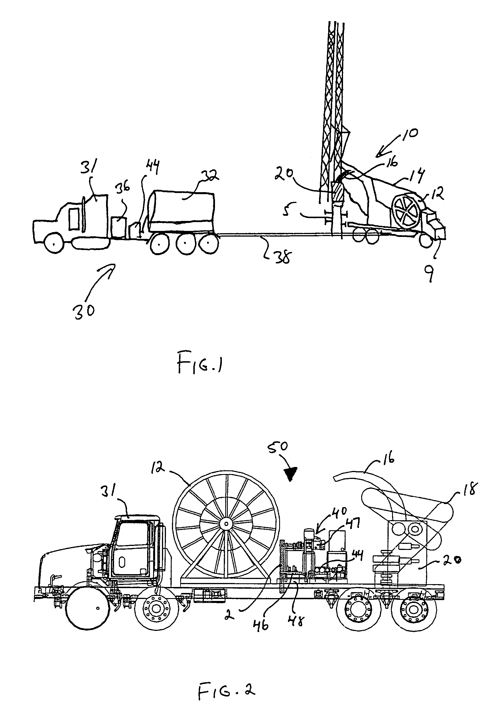
[0026]Reference is now made to the drawings. FIG. 1 shows prior art rigs and the ways these rigs are used. In particular, FIG. 1 shows a typical setup for a coil tubing unit 10 and a nitrogen rig 30.

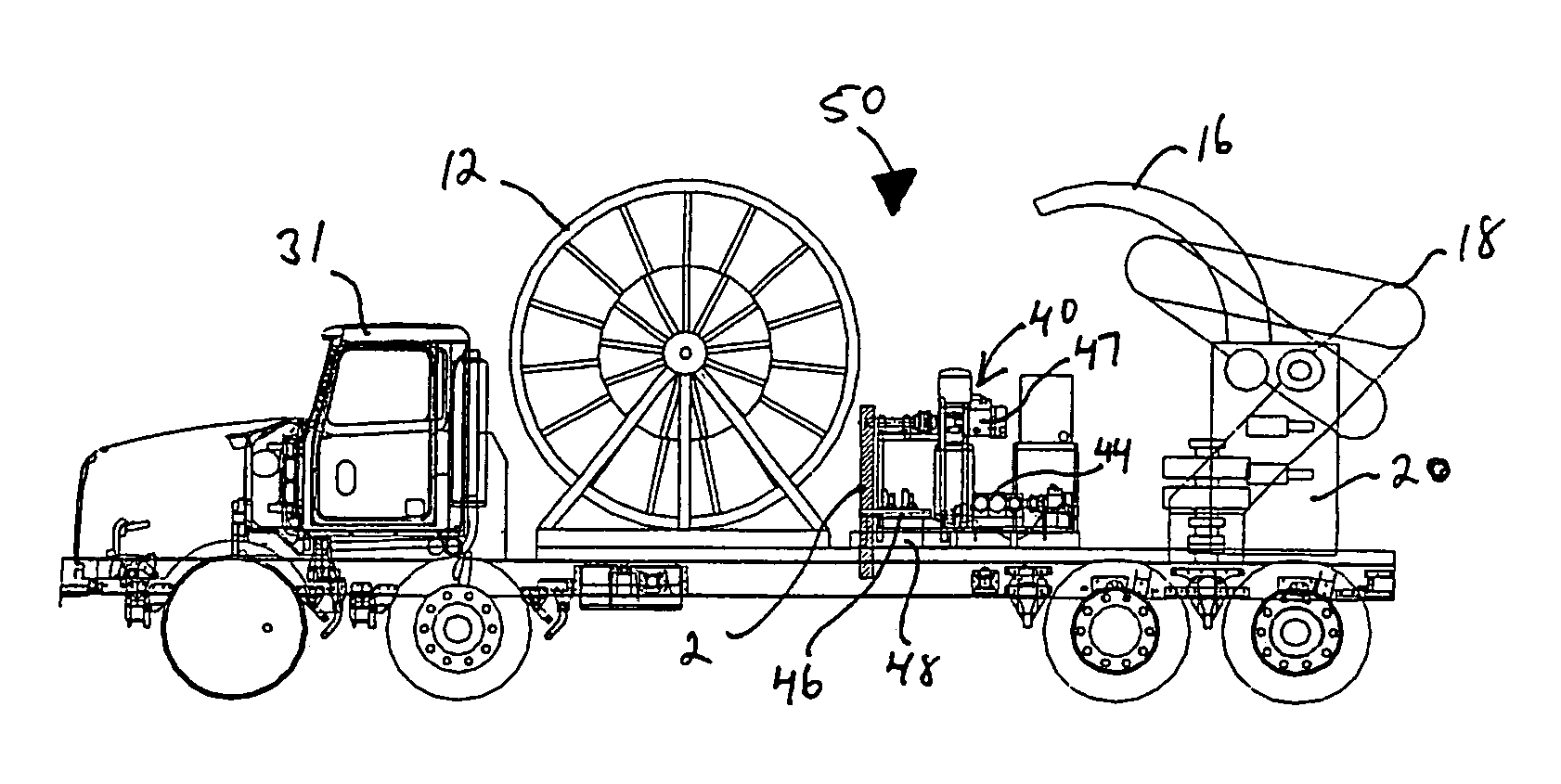
[0027]Coil tubing unit 10 is situated adjacent to wellhead 5. The rig consists of a mobile tractor / trailer unit 9 fitted with a spool 12 for coiled tubing 14, a boom mounted guide arch 16 and a tubing injector 20 that inserts and removes the coiled tubing from the well bore. As will be appreciated, the tubing unit is shown in its working position. For transport and storage, the boom 18 is used to withdraw the guide arch and injector into a stored position on top of the trailer as best seen in FIG. 2.

[0028]A conventional stand-alone nitrogen rig 30 includes its own tractor trailer 31 with the trailer supporting a tank 32 for liquid nitrogen, a flame fired heater 36 for vaporizing the nitrogen and a high pressure pump 44 for pumping liquid nitrogen from tank 32 into the heater and then int...


PUM


Abstract

Method and apparatus for servicing of a bore hole in the earth, comprising a first sub-assembly adapted for the insertion and removal of a continuous length of coiled tubing into and from the bore hole, a second sub-assembly adapted for the vaporization of liquified gas and the pumping of the resulting gas through the coiled tubing into the bore hole and a platform to support both the first and second sub-assemblies thereon.

Description

FIELD OF THE INVENTION[0001]The present invention relates to a coiled tubing unit for use in the servicing of oil and gas wells and more particularly to a unit mounted on a single mobile platform capable of providing both coiled tubing and pressurized fluid injection with non-fired heat recovery.BACKGROUND[0002]Well bores require periodic maintenance to remove for example accumulated sediments or for a host of other reasons well known in the industry. When maintenance is required, it is the usual practice to remove existing pumping equipment from the wellhead, and to move in a service rig to maintain control over the well during servicing and to inject and remove the necessary tools and equipment required to complete the maintenance or servicing operations.[0003]For well servicing and workovers, the use of coiled tubing is preferred. Coiled tubing is a single length of continuous unjointed tubing spooled onto a reel for storage in sufficient quantity to exceed the maximum depth of t...

Claims


Application Information

Patent Timeline
Patent Type & Authority Patents(United States)
IPC IPC(8): E21B21/16E21B36/00E21B37/00E21B19/22E21B43/16
CPCE21B19/22E21B43/166
Inventor FOSTER, ROBERT JOSEPHCOSTALL, DOUGLAS
Owner LEADER ENERGY SERVICES
Why Eureka
Try Eureka