Method, apparatus, header, and composition for ground heat exchange

a technology of ground heat exchange and header, applied in special-purpose vessels, lighting and heating apparatus, applications, etc., can solve the problems of ineffective horizontal loop, inability to use methods in urban areas, and eventually failure of metal pipe loop installations

Active Publication Date: 2010-09-02
RYGAN CORP
View PDF35 Cites 30 Cited by
  • Summary
  • Abstract
  • Description
  • Claims
  • Application Information

AI Technical Summary

Benefits of technology

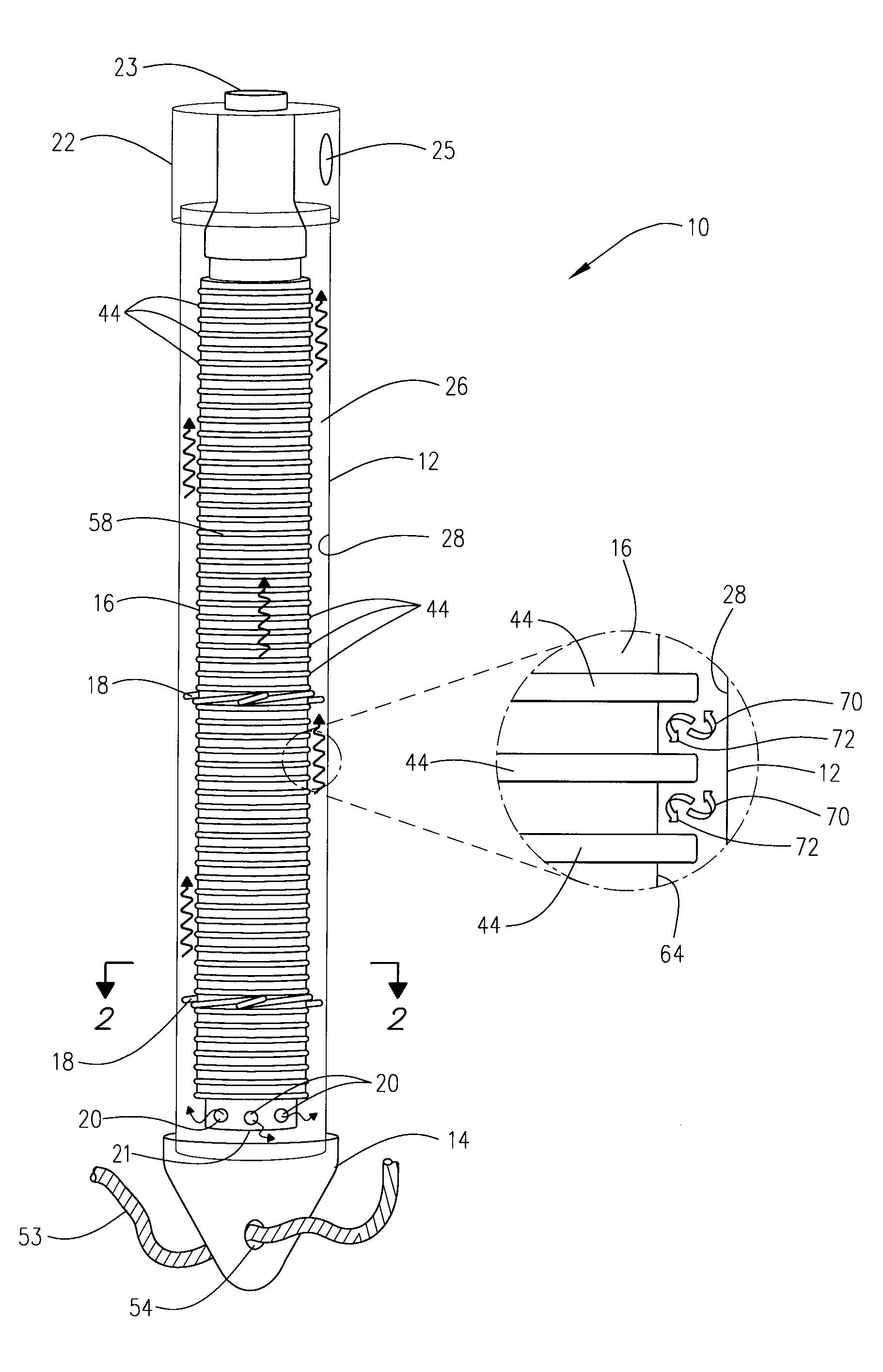
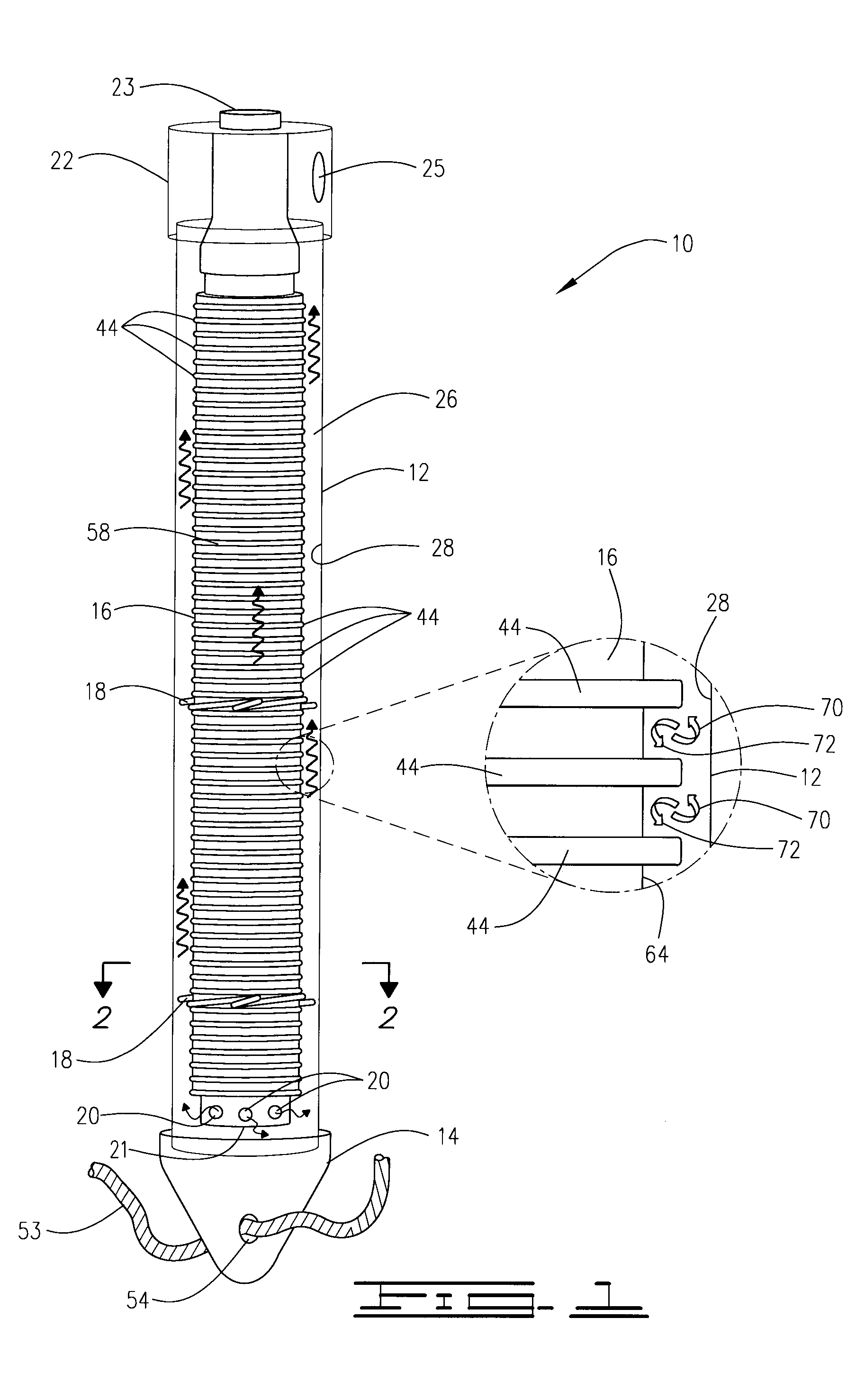
[0025]In addition, the present invention provides an improved supply and return header and an improved concentric ground exchange assembly having the inventive supply and return header installed on the upper end thereof. The inventive supply and return header satisfies the needs and alleviates the problems discussed above by: (a) eliminating the flange connection to the casing required by the prior art header; (b) replacing the flange connection with a header skirt or collar which is chemically fused directly to the upper end of the casing; and (c) significantly reducing the height of the header to as little as ⅓ or less of the height of the prior art structure so that significantly less trenching and digging is required when installing the inventive system. The inventive supply and return header therefore has a much greater life, is much more reliable, is much better able to withstand surface vehicular loads, and is less costly and much easier to install.
[0062]In another aspect, there is provided a grout composition that will not contaminate the environment.

Problems solved by technology

Experience has shown that horizontal loops are inefficient ground loops because the shallow depth of burial causes the ambient soil temperature to track the surface ground temperature.
This method can be no longer used in urban areas due to drinking water safety standards enacted to prevent aquifer contamination.
Initially, metal pipe loops were used in both concentric and U-tube installations to save capital cost, but experience has shown that metal pipe loop installations eventually fail due to anodic corrosion from conducting telluric or man-made electrical currents from one formation layer to another.
Experience has also shown that plastic ground loop installations can last indefinitely, but the local ground temperature will heat up or cool down if the seasonal load is not balanced.
Refrigerants such as Freon® typically are not used due to expense and possible aquifer contamination.
This undesirable condition is known as thermal short circuit.
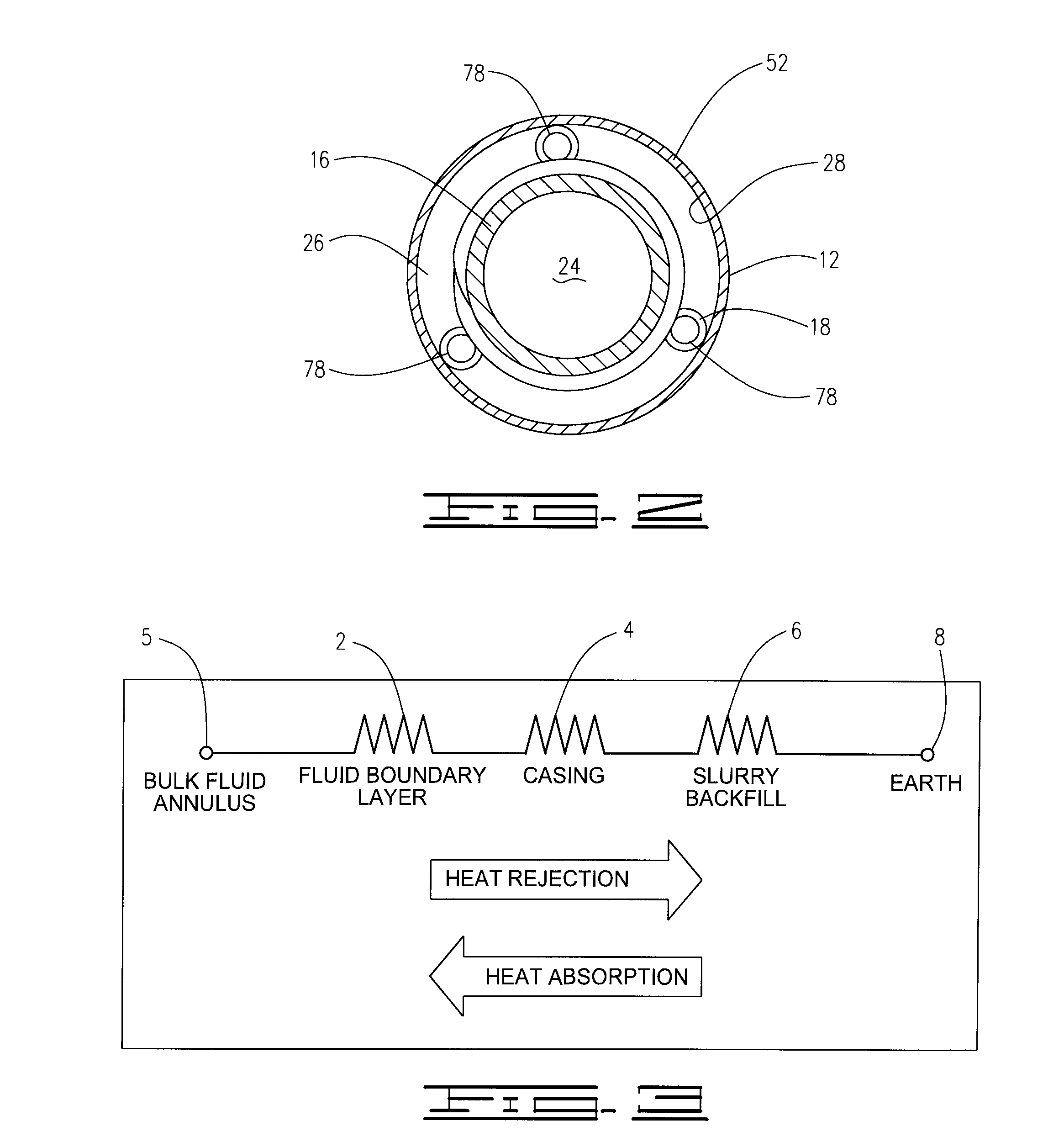
Prior U-tube designs have been particularly inadequate in minimizing thermal short circuit while prior concentric pipe designs have been particularly inadequate in minimizing thermal resistance of the grout and pipe wall.
U-tube designs do not have enough water storage volume or high enough pulse heat transfer to make a thermal bank.
Cost effectively manufacturing such a pipe with helical fliting disposed along the entire length of the outer surface has proven difficult and such fliting, and pipe, are easily damaged, making the flited pipe difficult to insert into a larger diameter pipe.
Attaching the fliting as a separate piece to a smooth pipe makes the fliting susceptible to slipping along the outer surface of the pipe, which would allow the smaller diameter pipe to come in contact with the larger diameter pipe, thus creating low flow zones.
Metal pipe offers very low thermal resistance, but corrosion resistant alloys are very expensive, and their weight makes them more expensive to ship and more difficult to install.
The prior art is inadequate in providing details specifying a backfill composition that would be pumpable, would enable sufficiently long set times for deployment, and would resist dissipation due to high ground water flow rates.
U.S. Pat. No. 4,574,875 does not address backfill composition and US Patent Application Publication No. 20070029066 prefers the use of thermally conductive cement but is not specific in backfill mixture composition, nor does it address permeability, environmental safety or dissipation.
The design in U.S. Pat. No. 4,574,875 offers no solution while the design in US Patent Application Publication No. 20070029066 prefers relying on laminar flow in the center channel or using an insulating gas within the smaller diameter pipe, which are both impractical solutions to implement.
The designs in both U.S. Pat. No. 4,574,875 and US Patent Application Publication No. 20070029066 also fail to provide solutions that: (1) minimize pressure drop across the system; (2) prevent blockage of the center channel outlet; and (3) facilitate installation.
In addition to the above, further shortcomings and problems with existing concentric ground exchange assemblies arise due to the design of the heat transfer fluid supply and return headers currently used in these systems.
Again, although refrigerants such as FREON® or other materials can alternatively be used, such materials are typically not employed due to the cost of materials and the danger of aquifer contamination.
Unfortunately, the supply and return header 112 used in the prior art concentric ground exchange assembly 102 has presented numerous problems and difficulties.
In addition to other shortcomings, the underground flange connection required by the prior art supply and return header 112 is susceptible to significant leakage and other problems resulting from: (a) thermal contraction and expansion of the header material (typically high density polyethylene), (b) deterioration of the gasket 134 and / or the bolts 132 and associated nuts and washers, (c) the application of insufficient or excessive torque to the flange bolts 132 during installation, (d) torque created by surface vehicular loads, and / or (e) the loosening of the nuts and bolts over time.

Method used


Image

  • Method, apparatus, header, and composition for ground heat exchange
  • Method, apparatus, header, and composition for ground heat exchange
  • Method, apparatus, header, and composition for ground heat exchange

Examples


example 1

EXAMPLE 1

[0112]A grout slurry was formed by adding 246 g of treated water (consisting of 240 g water and 6 g sodium chloride) to a dry mix consisting of (a) 120 g of natural flake graphite having a particle size passing (i.e., less than) 200 mesh and (b) 40 g of sodium bentonite having a particle size passing 325 mesh. The salt content of the treated water was thus 2.44% by weight (equivalent to about 1.88 lb. NaCl per 9 gallons of water) and the solids content of the slurry product composition was about 40% by weight. The slurry product was pumpable and had a specific gravity of 1.25. After setting overnight, a layer of water had begun to form on top of the slurry composition by the following morning.

example 2

EXAMPLE 2

[0113]A grout slurry was formed by adding 152 g of treated water (consisting of 150 g water and 2 g sodium chloride) to a dry mix consisting of (a) 75 g of natural flake graphite having a particle size passing a 200 mesh screen and (b) 25 g of sodium bentonite having a particle size also passing a 200 mesh screen. The salt content of the treated water was thus 1.3% by weight (equivalent to 1 lb. of NaCl per 9 gallons of water) and the solids content of the slurry product composition was about 40% by weight. The slurry was more viscous, was not pumpable, was barely pourable, and had set up after one day. No water layer formed on the top of the composition.

example 3

EXAMPLE 3

[0114]A grout slurry was formed by adding 154 g of treated water (consisting of 150 g water and 4 g sodium chloride) to a dry mix consisting of (a) 75 g of natural flake graphite having a particle size passing a 200 mesh screen and (b) 25 g of sodium bentonite having a particle size passing 200 mesh. The salt content of the treated water was thus 2.6% by weight (equivalent to 2 lb. NaCl per 9 gallons of water) and the solids content of the slurry product composition was about 40% by weight. The slurry product was pumpable. After one day, the slurry was thicker, but still pourable, and 4 to 5 g of water had formed on the top of the composition.

[0115]These examples illustrate the effectiveness of the use of a thinning agent in accordance with the present invention for forming and delivering the inventive grout backfill composition. In regard to the use of sodium chloride, potassium chloride, or a mixture thereof as the thinning agent, these examples particularly show the eff...


PUM

PropertyMeasurementUnit
volumeaaaaaaaaaa
heightaaaaaaaaaa
heightaaaaaaaaaa

Abstract

A subterranean ground heat exchange system, a method of installation, and a grout composition therefor. The grout composition is a pumpable slurry formed of from about 70 to about 85 parts by weight natural flake graphite and from about 30 to about 15 parts by weight bentonite. The solids content of the pumpable grout slurry is preferably at least 35% by weight and is more preferably at least 40% by weight. The ground exchange apparatus preferably utilizes an improved supply and return header comprised of supply and return ports which are provided through the vertically extending outer wall of a header housing. The header also includes an interior supply conduit which extends from the supply port into the interior of the header housing and includes a bend positioned in the interior of the housing for directing the heat transfer fluid downwardly.

Description

[0001]This application is a continuation-in-part of pending U.S. patent application Ser. No. 12 / 259,878, filed Oct. 28, 2008, which claims the benefit of now expired U.S. Provisional Patent Application Ser. No. 61 / 042,912 filed on Apr 7, 2008. This application also claims the benefit of U.S. Provisional Patent Application Ser. No. 61 / 158,556 filed Mar. 9, 2009, and incorporates said Provisional Application Ser. No. 61 / 158,556 by reference into this document as if fully set out at this point.FIELD OF THE INVENTION [0002]This invention relates to the exchange of heat with the earth for heating, cooling and thermal energy storage applications. In one particular aspect, but not by way of limitation, the invention relates to cost effective materials, devices, systems, compositions, and methods which lower the thermal resistance between the working fluid (i.e., the heat exchange fluid) of a closed loop ground heat exchanger and the earth and to working fluid supply and return headers for ...

Claims


Application Information

Patent Timeline
Patent Type & Authority Applications(United States)
IPC IPC(8): F24J3/08F16L1/00C09K5/00
CPCC09K8/467F24J3/084F28F2013/006Y02E10/125F24J2003/088F24T10/17F24T2010/53F28F1/08Y02E10/10
Inventor LAWLESS, LANEFRAIM, MICHAELLARSON, BRANDON A.
Owner RYGAN CORP
Why Eureka
Try Eureka