
Culture swab with protective cap and safety pin

a technology of protective cap and safety pin, which is applied in the field of new veterinary devices or instruments, can solve the problems of increasing the cost of the final culture collection device product, affecting the quality of the final culture collection device, and the element that will ultimately collect the sample can be prematurely contaminated, so as to reduce the chance of contamination, facilitate the collection of samples, and facilitate the storage of the device.

Inactive Publication Date: 2005-12-29
CONTINENTAL PLASTICS
View PDF55 Cites 47 Cited by
  • Summary
  • Abstract
  • Description
  • Claims
  • Application Information

AI Technical Summary

Benefits of technology

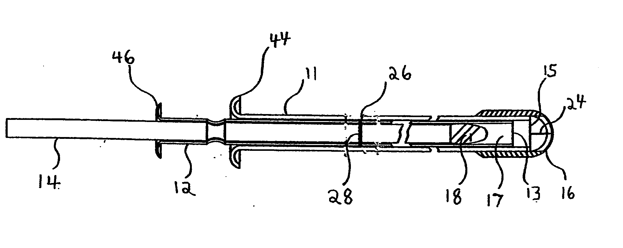
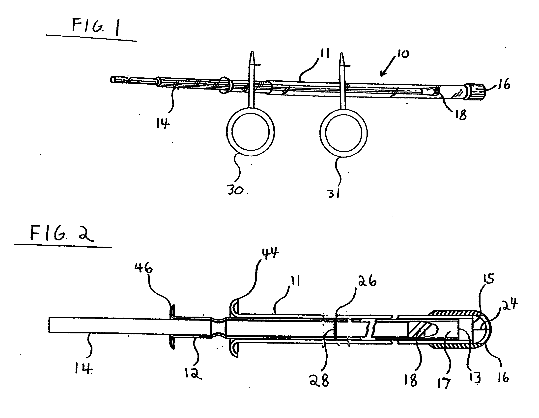
[0011] A primary object of the invention is to provide an improved culture collection device or insemination instrument that isolates and protects the inner portion of the device upon its insertion into or removal from the interior of the body or cervix of an animal and to sealingly retain this element for subsequent handling and transport to the analysis laboratory. Another objective of the invention is to incorporate a manufactured cap in the instrument that lessens the chance of contamination to the sample or tube and inner areas of the animal by eliminating areas of entrapment of foreign material on the device's protective cap and also makes collection of a sample easier by providing a protective cap medium that requires a consistent force to be breached when the swab is being applied to the sample area inside the animal. Another object of the invention is to make manufacture of such devices cheaper and more efficient by use of incorporating the manufactured cap into the device. A further object of the invention is to make transport, handling, and storage of the device safer by including at least one safety pin in the device, which prevents premature deployment of the sample taking members.
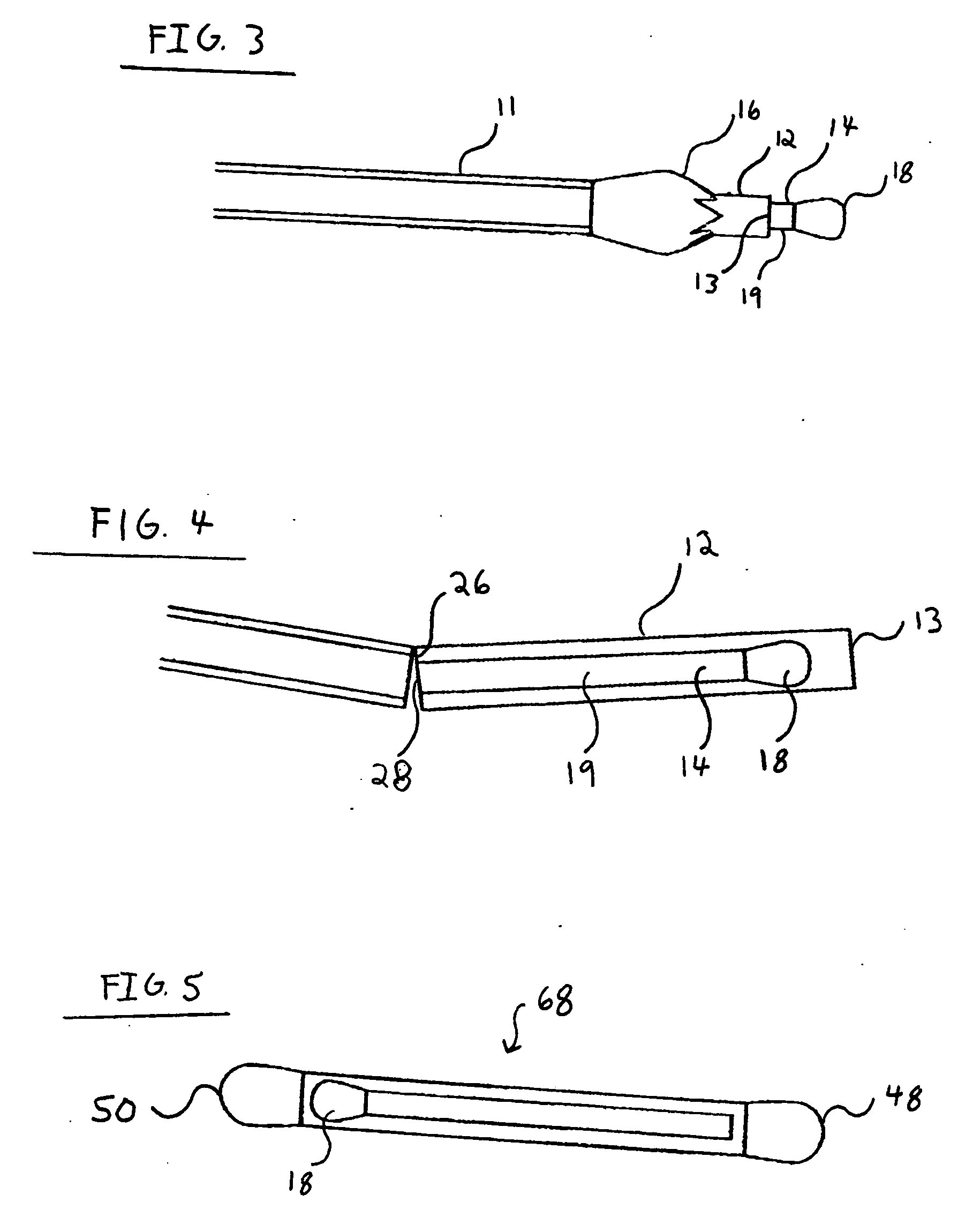
[0013] Once the sample is taken, the swab is retracted back into the second inner member and the second inner member, with the first inner member inside, is retracted back to its original position inside the outer member. After the swab and second inner member are again isolated inside the outer member, the entire device is removed from the animal. The swab, now containing the sample, is then preserved for testing by removing the second inner member and the enclosed first inner member from the outer tube and then capping the open first end of the second inner member, which is no longer enclosed by the outer member. The second inner member, which protects the swab of the first inner member, has a scored section, located bellow the point where the swab inside is positioned, that completely circumvents the second inner member and allows for the second inner member to be easily and cleanly broken at the scored section. The enclosed elongated tube or rod of the first inner member also has a scored section that is aligned with the scored section of the second inner member while the device is in its retracted position, and this scored section allows the first inner member to break contemporaneously with, and at the same point, as the second inner member when second inner member is broken. The broken end of the second inner member is then capped on the broken end so that it is now capped on both ends and contains the broken off end of the first inner member and its swab element inside. The user now has a sealed and sanitary holder for the swab element that prevents contamination of the sample and facilitates transportation and storage for later testing.
[0014] Additionally, a preferred embodiment also can have one or more safety pins that prevent the first inner member, second inner member, and outer member from moving longitudinally in relation to each other before the safety pins are removed. These pins are meant to protect from the inner members shifting in a manner that would permit the second inner member, and enclosed first inner member, to breach the outer member's protective cap before the user is ready to deploy the device to collect a sample. The use of these safety pins makes shipping and handling of the items safer and ensures the device cannot be employed until the pins are removed. This feature is important as the device is only good for one use, and the device must be discarded if the protective cap is breached while the instrument is outside of the animal.
[0018] In another embodiment of the invention, the ring of the first safety pin is connected to the projection of the safety pin so that the plane of the ring is at about a forty-five degree angle in relation to the projection. This configuration allows the operator of the device to grip and use the device like a syringe when pushing the second inner member through the protective cap. The user puts his thumb through the pin ring and then puts his index and middle fingers on the first flange so that the device is between the two fingers. By bringing his thumb and index and middle fingers together as if using a syringe, the operator can more easily force the second inner member to break through the protective end cap while deploying the device. This embodiment is especially useful when the device is for artificial insemination.

Problems solved by technology

Thus, previously recognized problems have been that when the instrument is inserted into the animal the culture collection instrument can transport infectious contaminants from the vulva and / or cervical canal into the cervix of the animal, or the element that will ultimately collect the sample can be prematurely contaminated before reaching the area that is the actual subject of the culture collection.
Despite past improvements in the art, prior designs did not completely eliminate the contamination problems associated with collecting a culture of insemination.
The method of manufacturer of this cap resulted in a further disadvantage in that the hand made nature of the process was costly, time consuming, and unable to be automated, which all led to increased costs for the final culture collection device product.
These prior methods of production also led to a further undesired characteristic of the instruments in that the force required to push the inner members through the protective cap varied substantially among individual devices.
The inconsistent force required to employ the sample taking element frustrated ease of use because product purchasers could never become familiar with a consistent method of use.
An additional limitation of the prior art is that the devices could be prematurely deployed.
When this occurs, the device is effectively useless because the sample collecting element is not sufficiently protected from contamination once the protected cap is breached.

Method used


Image

  • Culture swab with protective cap and safety pin
  • Culture swab with protective cap and safety pin
  • Culture swab with protective cap and safety pin

Examples


Embodiment Construction

[0036] The present invention and the various features and advantageous details thereof are explained more fully with reference to the non-limiting embodiments described in detail in the following description.

[0037] The construction of a culture collection device, such as disclosed in the present inventor's prior U.S. Pat. No. 4,586,604 and U.S. Pat. No. 4,457,313 is well-known to those skilled in the art and therefore a detailed description thereof is not necessary to fully understand the present invention, which is directed to novel improvements in the construction of the protective cap 16 and the addition of one or more elements, specifically on or more safety pins 30 and 31.

[0038] The invention is shown in FIGS. 1 and 2 which depict a veterinary device or instrument 10 that is comprised of an outer member 11, preferably a plastic tube, which has a protective cap or tip 16, preferably a injection molded plastic cap, on its first end. When used as a collection device 100, the dev...


PUM

PropertyMeasurementUnit
angleaaaaaaaaaa
angleaaaaaaaaaa
diameteraaaaaaaaaa

Abstract

A veterinary instrument for use in animal husbandry that includes an inner member with a swab or similar element attached at one end, located inside a second inner member meant to protect the innermost member and attached swab, and an outermost member that surrounds both inner members and has a closed mold manufactured protective cap on one end. The instrument has one or two safety pins which ensure that the instrument cannot be used until they are removed.

Description

BACKGROUND OF THE INVENTION [0001] 1. Field of the Invention [0002] The present invention relates to a novel veterinary device or instrument useful in medication, antiseptic, culture collection, and artificial insemination processes utilized in animal husbandry. More particularly, the present invention relates to a veterinary instrument and sealed holder having improvements to the cap and the holding tube that make the device function more effectively and lower the cost and time of manufacturing. [0003] 2. Discussion of the Related Art [0004] U.S. Pat. No. 4,586,604 to Alter and entitled “Culture Collection Instrument and Sealed Swab Holder Therefor” discloses one device in the prior art. U.S. Pat. No. 4,457,313 to Alter entitled “Shield Protector for Artificial Insemination and Culture Collection Instruments” discloses another. The disclosure of each of these patents in its entirety is hereby expressly incorporated by reference into the present application for the purposes of indic...

Claims


Application Information

Patent Timeline
Patent Type & Authority Applications(United States)
IPC IPC(8): A61B10/00A61B10/02A61B19/00A61D1/00A61D19/02A61F13/38B29C45/00G01N1/02
CPCA61B10/0291A61D1/00A61B2019/308A61B2090/038
Inventor ALTER, RICHARD RAYMOND
Owner CONTINENTAL PLASTICS
Learn More