System for bi-directionally controlling the cryo-tip of a cryoablation catheter

Inactive Publication Date: 2005-12-29
CRYOCOR
View PDF62 Cites 81 Cited by
  • Summary
  • Abstract
  • Description
  • Claims
  • Application Information

AI Technical Summary

Benefits of technology

[0013] In another aspect of the invention, the system includes a mechanism that is operable on the pull wires for delaying an application of tension on one of the pull wires until at least a portion of any tension on the other pull wire is released. This delay allows for the recovery of large deflections. For the case where CW and CCW reels and a drive cog are used to control the pull wires, the delay mechanism can be implemented by

Problems solved by technology

Moreover, this manipulation typically must be performed within a relatively limited space (e.g. the left atrium).
For these conventional systems, a change in deflection from one direction to another can be problematic.
However, when the deflec

Method used


Image

  • System for bi-directionally controlling the cryo-tip of a cryoablation catheter
  • System for bi-directionally controlling the cryo-tip of a cryoablation catheter
  • System for bi-directionally controlling the cryo-tip of a cryoablation catheter

Examples


Embodiment Construction

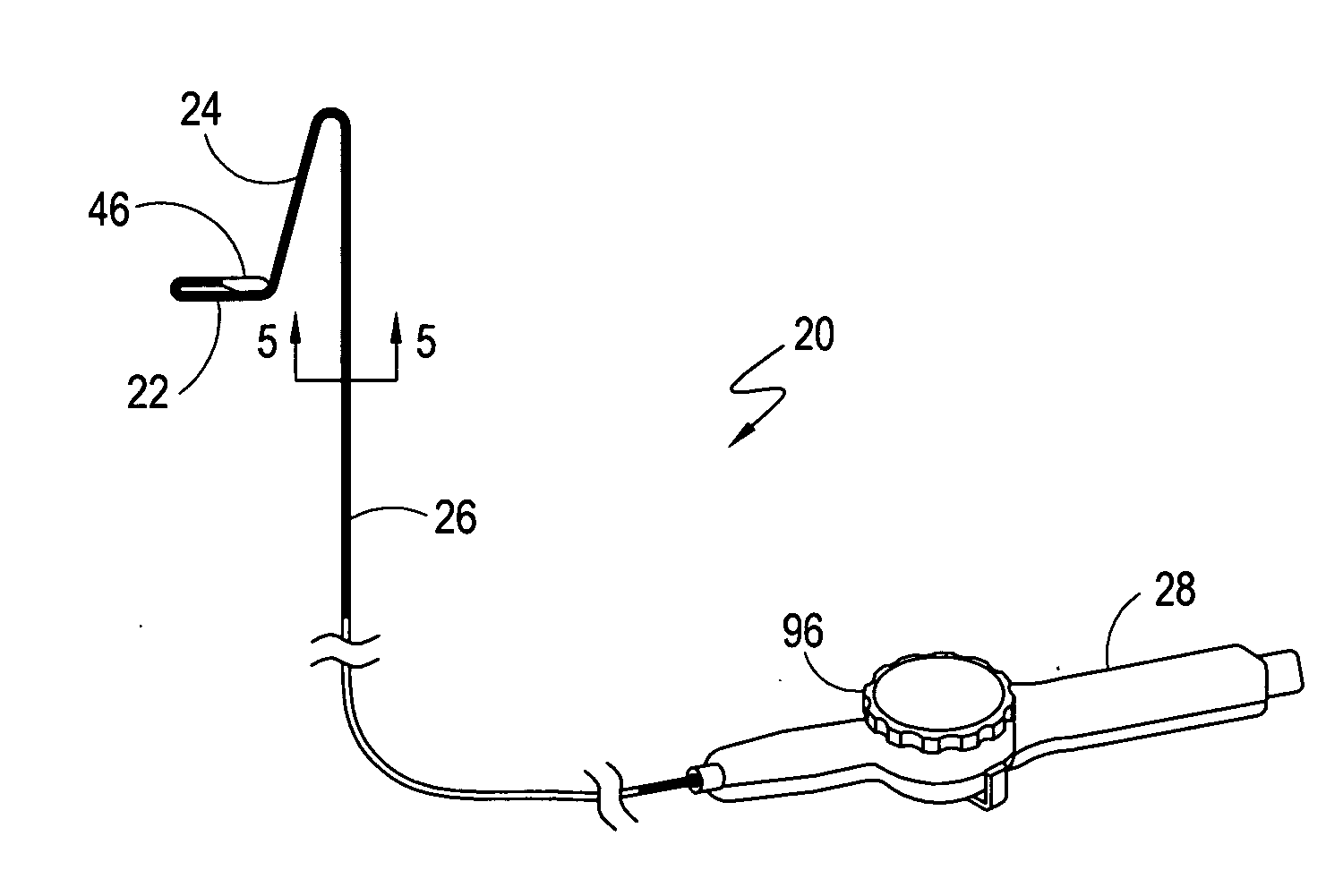
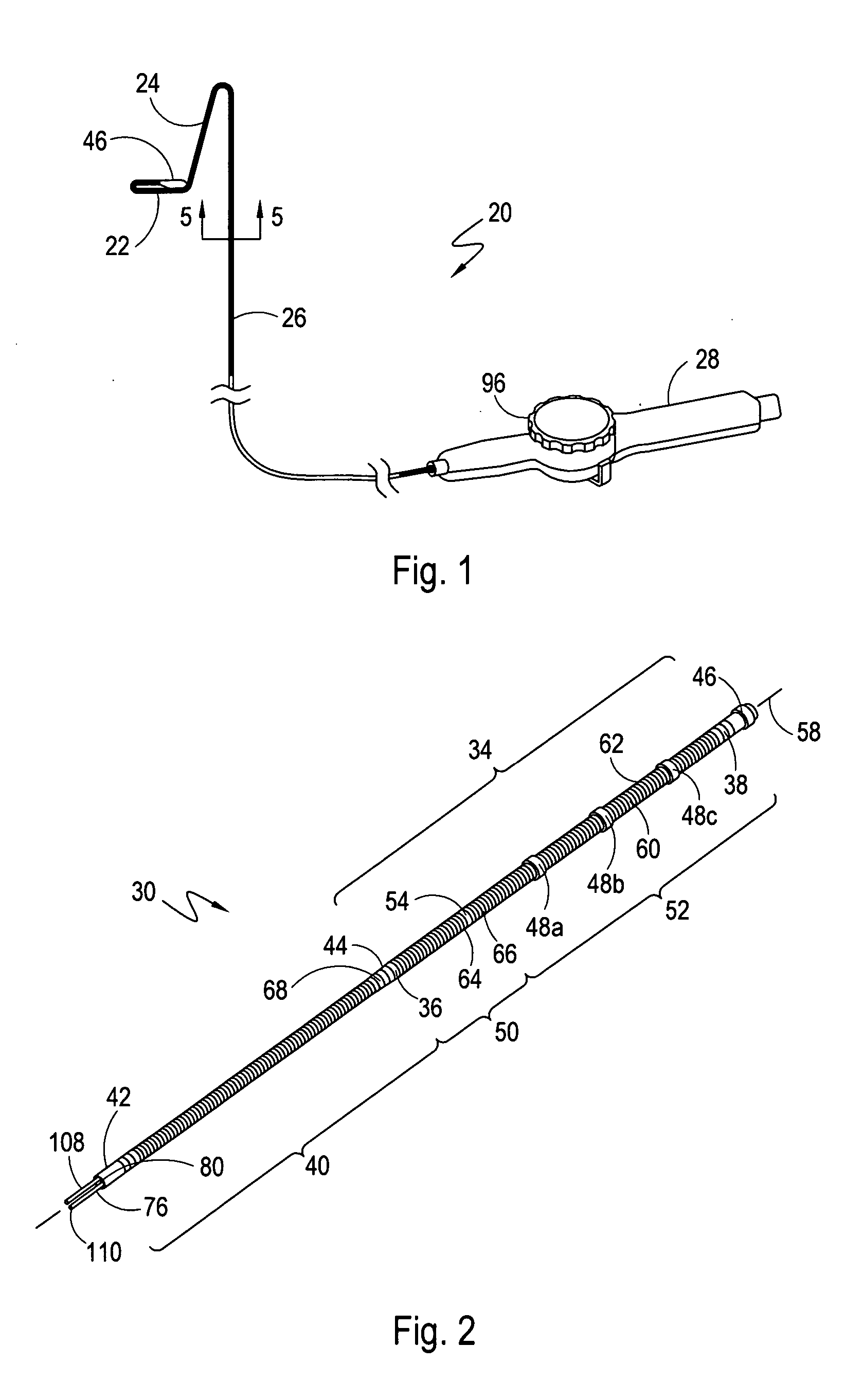
[0026] Referring initially to FIG. 1, a cryo-catheter for cryoablating a lesion in a body conduit of a patient is shown and generally designated 20. As indicated in FIG. 1, the cryo-catheter 20 can be manipulated into different configurations and orientations. To do this, the cryo-catheter 20 includes a system for deflecting a section 22 of the cryo-catheter 20 into a hoop configuration, as shown. It also includes a bi-directional control system for deflecting a section 24 of the cryo-catheter 20 in both a first direction and a second direction that is substantially coplanar and opposite the first direction. FIG. 1 further shows that the cryo-catheter 20 includes an elongated catheter body 26 that extends distally from a catheter handle 28. Although these deflecting systems are shown and disclosed herein as being part of a cryo-catheter 20, those skilled in the pertinent art will appreciate that these systems can be used as well in other types of catheters where bi-directional contr...


PUM


Abstract

A bi-directional system for actively deflecting the distal tip of a catheter includes a reconfigurable tube that is positioned proximal to the catheter's distal tip. The tube is formed with slits that are arranged to allow the tube to be transformed from a relaxed, cylindrical configuration to a plurality of deflected configurations. First and second pull wires are provided, with each wire having a respective distal end that is attached to the distal end of the tube. Each wire extends to a catheter handle where it is attached to a respective reel. The reels can be rotated, back and forth, to selectively deflect or relax the tube. To ensure a smooth recovery after a relatively large deflection, a mechanism is disclosed for delaying an application of tension on one of the pull wires until at least a portion of any tension on the other pull wire is released.

Description

FIELD OF THE INVENTION [0001] The present invention pertains generally to systems and methods for actively deflecting a distal portion of a catheter while the distal portion is positioned within a body conduit. More particularly, the present invention pertains to a bi-directional system for deflecting the distal portion of a catheter. The present invention is particularly, but not exclusively, useful as a system for bi-directionally controlling the cryo-tip of a cryoablation catheter. BACKGROUND OF THE INVENTION [0002] Atrial fibrillation is an irregular heart rhythm that adversely affects approximately 2.5 million people in the United States. It is believed that at least one-third of all atrial fibrillation originates near the ostium of the pulmonary veins. Anatomically, two pairs of pulmonary veins are connected to the left atrium of the heart with each pair delivering blood to the heart from one of the patient's lungs. [0003] It is further believed that the optimal technique to t...

Claims


Application Information

Patent Timeline
IPC IPC(8): A61B17/00A61B18/02A61M31/00A61M37/00
CPCA61B18/02A61B2017/003A61B2018/0212A61B2018/0262A61M2025/0161A61M25/0136A61M25/0138A61M25/0147A61M25/0043
Inventor KOERNER, RICHARD J.LENTZ, DAVID J.O'DONNELL, JOSEPH A.SALINAS, ALVIN B.
Owner CRYOCOR
Why Eureka
Try Eureka