
Compact modular embedded device

a modular, embedded technology, applied in the direction of electrical apparatus casings/cabinets/drawers, instruments, computer control, etc., can solve the problems of limiting the application which may be run on the embedded device, the memory footprint of an application, and the situation may be exacerbated, so as to facilitate the development of compact modular devices, the effect of unprecedented size and functionality

Active Publication Date: 2005-12-29
NATIONAL INSTRUMENTS
View PDF9 Cites 65 Cited by
  • Summary
  • Abstract
  • Description
  • Claims
  • Application Information

AI Technical Summary

Benefits of technology

The patent describes a new technology for creating small, modular embedded devices that can perform various functions. These devices can be powered by batteries, have low power consumption, and are easy to program and maintain. They can be connected together using a modular architecture, and may require additional modules for added functionality. The devices can be used in various scenarios and are designed to be easily programmed and standalone. The technology allows for the creation of compact, modular embedded devices that are efficient, flexible, and require minimal maintenance.

Problems solved by technology

However, in many prior art systems it is often the case that the memory footprint of an application, e.g., a program, e.g., a graphical program, is too large to be stored and executed on an embedded device.
This situation may be exacerbated by the fact that an execution system and / or operating system required to execute the application may also have a relatively large footprint in the target embedded device, thereby limiting further the applications which may be run on the device.
While personal computers (PCs) or workstations are relatively inexpensive for the amount of computational power they provide, they are still generally more expensive and larger than the cheapest and smallest embedded systems.
Requirements for system size and power consumption of some systems cannot be met by existing standard embedded hardware.
Alternatively, the user interface may be used merely to view the input and output, or just the output, and the input may not be interactively manipulable by the user during program execution.

Method used


Image

  • Compact modular embedded device
  • Compact modular embedded device
  • Compact modular embedded device

Examples


example process

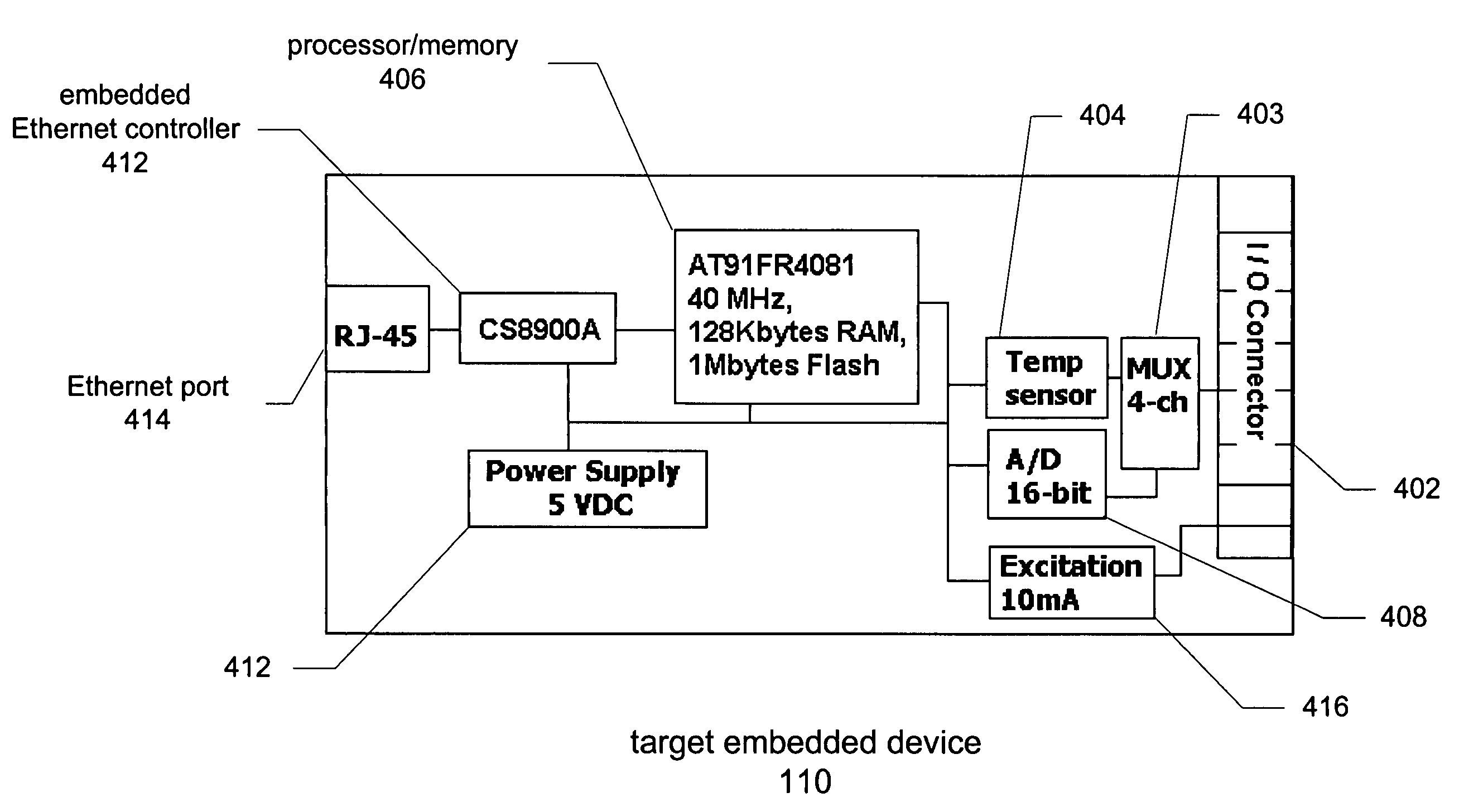
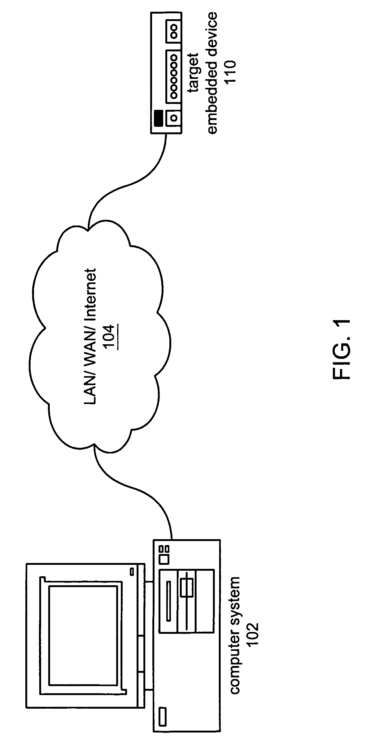
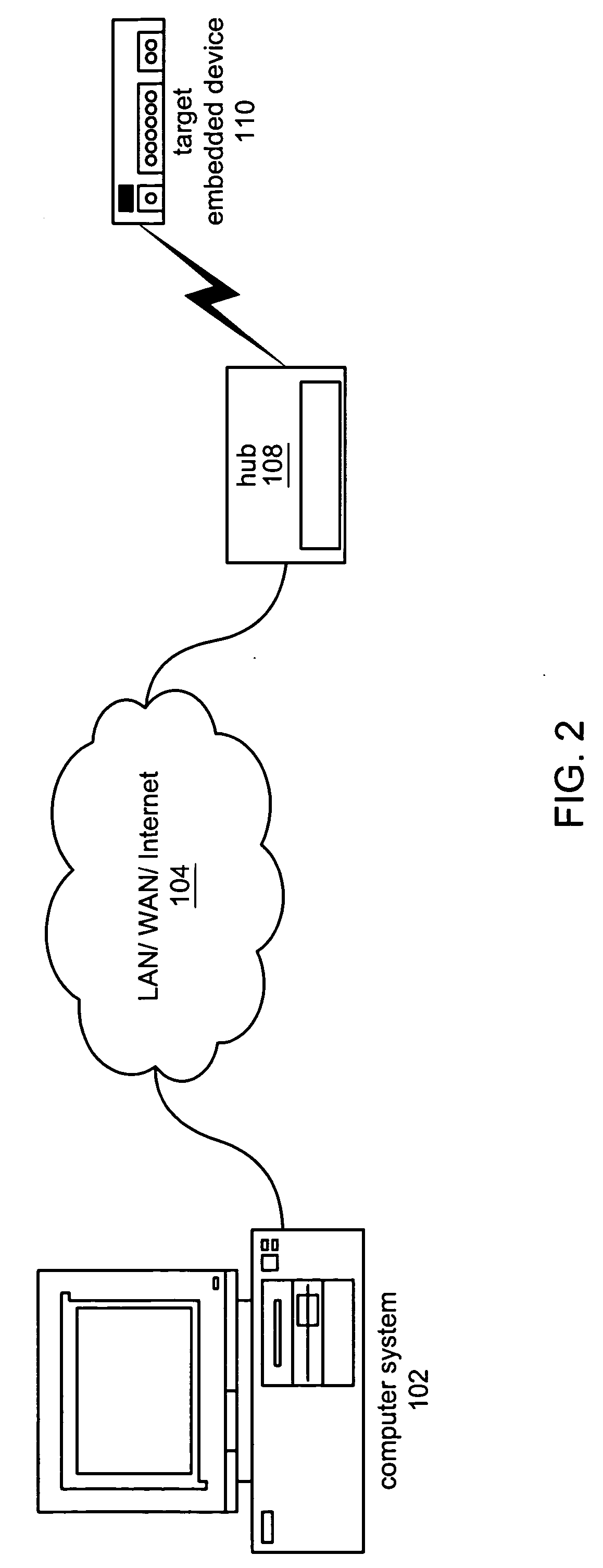
[0378] The following is a simple example of one embodiment of the above described processes. In this example, the user creates a VI on the host computer 102, named Delay.vi, and wishes to run this VI on the target device 110.

[0379] On the host computer 102, the VI is transformed into an object file named Delay.o. The modules required for running the VI are determined by a dependency checker executing on the host computer 102, producing the following list (for example): [0380] uClibc / memmove.o (from directory uClibc take file memmove.o) [0381] cookie / mbCookie.o [0382] occur / mbOccur.o [0383] uClibc / memcpy.o

[0384] So at this point, the application VIs are converted into object files, and the required modules (that are also compiled into object files at this point) from the modular callback system 1906A are determined. Then, all the object files pertaining to the application (using an ordinary C linker) are lined into a single object file which becomes the “application object file”. I...


PUM


Abstract

A compact modular embedded device. A base module includes a processor, a memory medium operable to store a bootloader for executing graphical programs, a buss and a power input coupled to the processor, memory medium, and bus, for receiving power from a power source and providing the received power to the processor, memory medium, and bus. The base module can couple to a host computer via a transmission medium, receive a program from the host computer, and store the program in the memory medium. The base module may couple to extension modules via the bus in a stacked fashion, where the base module and the extension modules each include a respective substantially planar circuit board that when stacked are substantially parallel. Each extension module provides respective functionality for the device. The base module can execute the program to perform a function in conjunction with the extension modules.

Description

COPYRIGHT NOTICE [0001] A portion of the disclosure of this patent document contains material which is subject to copyright protection. The copyright owner has no objection to the facsimile reproduction by any one of the patent disclosure, as it appears in the Patent and Trademark Office patent files or records, but otherwise reserves all copyright rights whatsoever. FIELD OF THE INVENTION [0002] The present invention relates to the fields of embedded devices, and more particularly to an extensible compact modular embedded device. DESCRIPTION OF THE RELATED ART [0003] Embedded measurement and control systems have been developed for a wide variety of applications, such as automated manufacturing and remote data collection, among others. However, in many prior art systems it is often the case that the memory footprint of an application, e.g., a program, e.g., a graphical program, is too large to be stored and executed on an embedded device. This situation may be exacerbated by the fac...

Claims


Application Information

Patent Timeline
Patent Type & Authority Applications(United States)
IPC IPC(8): G06F1/18G06F13/00
CPCG06F8/51G06F1/183
Inventor GHERCIOIU, MARIUSHEDESIU, HOREAFOLEA, SILVIUCRISAN, GRATIAN I.CETERAS, CIPRIANMONOSES, IOAN
Owner NATIONAL INSTRUMENTS
Learn More