Storage-volume fuel injection system for an internal combustion engine

a fuel injection system and internal combustion engine technology, applied in the direction of positive displacement liquid engines, electric control, piston pumps, etc., can solve the problems of difficult installation on the engine, discharging thermal energy, and normal bulkiness, and achieve the effect of eliminating the drawbacks of known systems, optimizing performance, and high reliability

Active Publication Date: 2006-01-05
CENT RICERCHE FIAT SCPA
View PDF18 Cites 20 Cited by
  • Summary
  • Abstract
  • Description
  • Claims
  • Application Information

AI Technical Summary

Benefits of technology

[0012] It is an object of the present invention to provide a fuel injection system, which is highly reliable and el...

Problems solved by technology

Such a common rail, however, is normally extremely bulky and therefore difficult to install on the engine.
These known systems have the drawback of keeping the pump operating permanently at maximum flow, since the bypass solenoid valve provides simply for draining into the tank the fuel pumped in excess of that drawn by the injectors, thus dissipating thermal energy.
The size of the storage volume, however, does not allow an acceptable reduction in start-up time, so that fuel is injected at less than optimum pressure, thus resulting in poor combustion at the initial engine operating stage.
This practice has the draw...

Method used


Image

  • Storage-volume fuel injection system for an internal combustion engine
  • Storage-volume fuel injection system for an internal combustion engine
  • Storage-volume fuel injection system for an internal combustion engine

Examples


Embodiment Construction

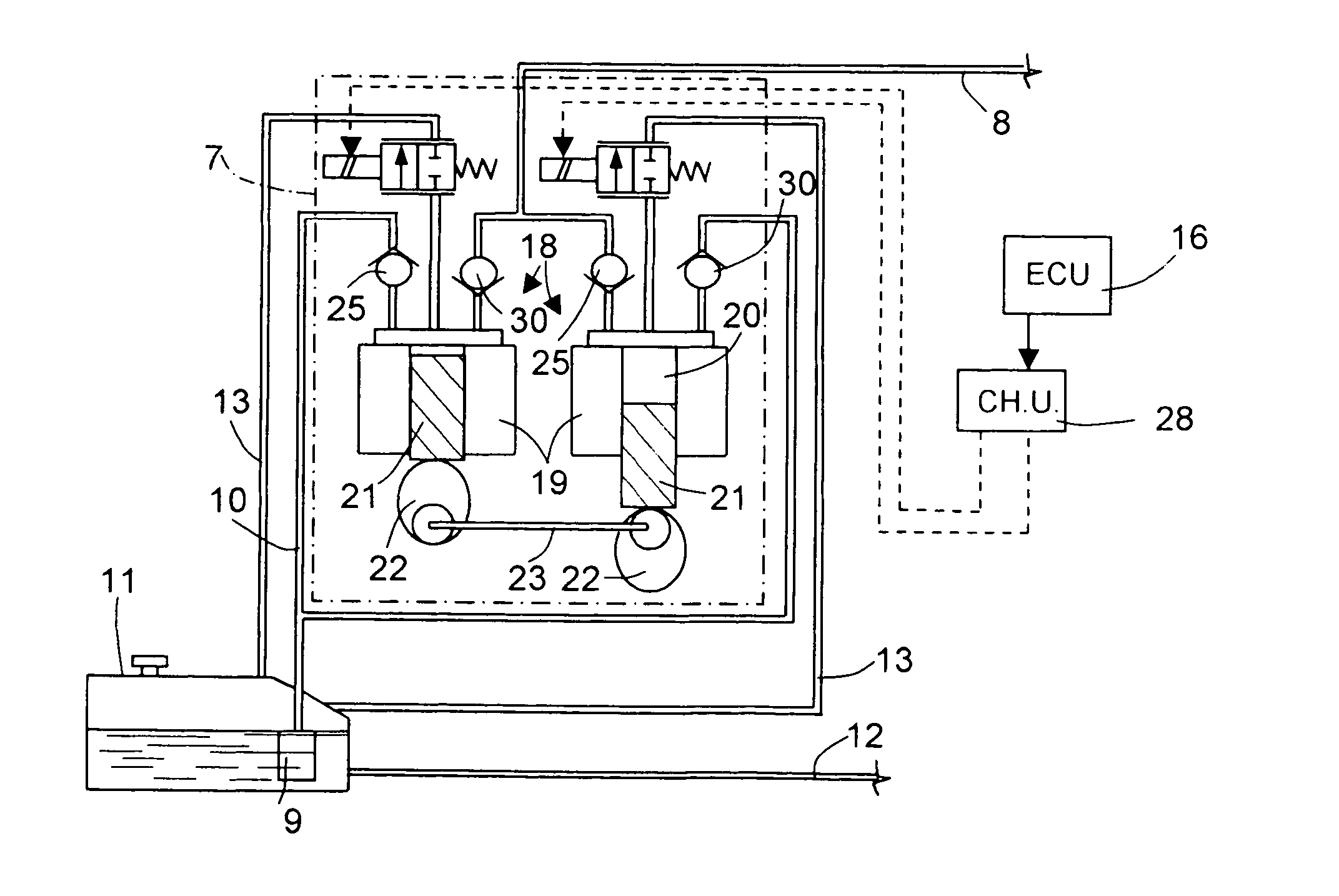
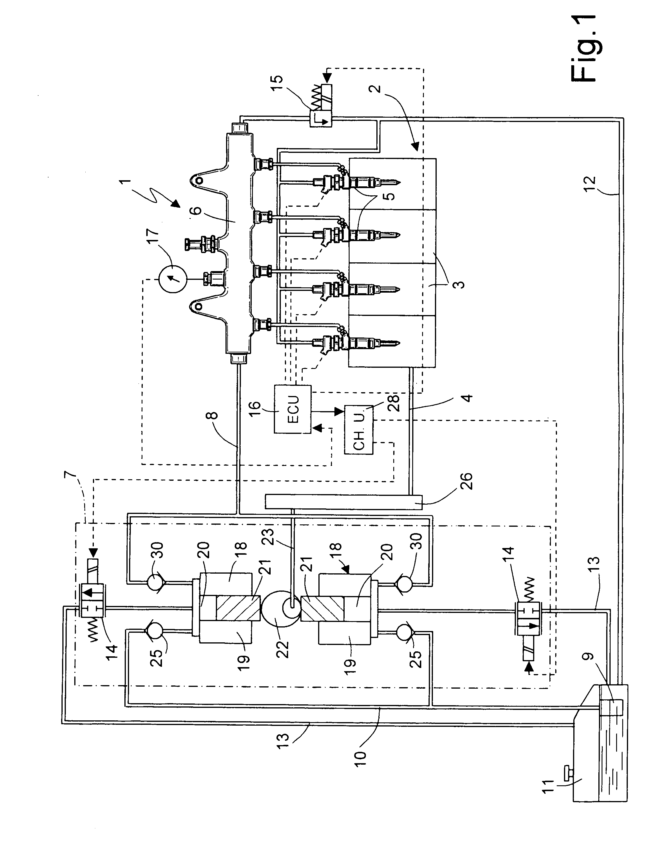
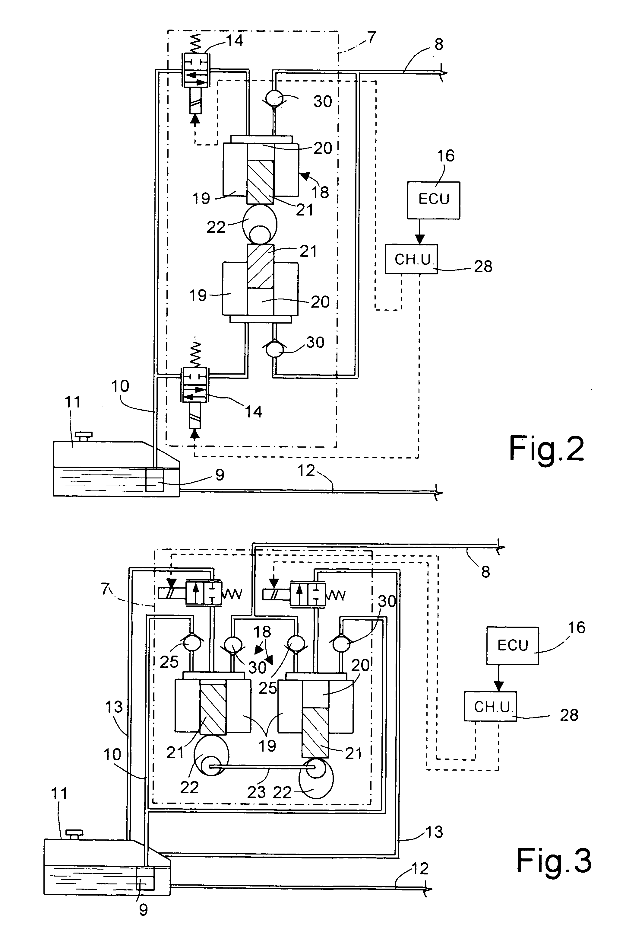
[0025] With reference to FIG. 1, number 1 indicates as a whole a common rail fuel injection system for an internal combustion, e.g. diesel, engine 2. Engine 2 comprises a number of, e.g. four, cylinders 3 which cooperate with corresponding pistons (not shown) to rotate a drive shaft 4.

[0026] Injection system 1 comprises a number of electric injectors 5 associated with, and for injecting high-pressure fuel into, cylinders 3. Injectors 5 are connected to a storage volume having a given volume for one or more injectors. In the embodiment shown, the storage volume is defined by a common rail 6, to which injectors 5 are all connected. Common rail 6 is supplied with high-pressure fuel by a high-pressure pump—indicated as a whole by 7—along a high-pressure delivery line 8. High-pressure pump 7 is in turn supplied by a low-pressure pump, e.g. a motor-driven pump 9, along a low-pressure-fuel intake line 10. Motor-driven pump 9 is normally located in the fuel tank 11, in which terminates a d...


PUM


Abstract

The injection system (1) includes a pump (7) for supplying high-pressure fuel to a storage volume, defined for example by a common rail (6), for supplying a number of injectors (5). The pump (7) has at least one reciprocating pumping member (18) with a sinusoidal compression stroke (24). The injection system (1) includes at least one bypass solenoid valve (14) controlled by a control unit (16) having a chopper unit (28) for producing multiple deliveries (29, 31) at each compression stroke (24), so that the pressure in the common rail (6) is substantially level. Each pumping member (18) may be associated with a corresponding bypass solenoid valve (14).

Description

BACKGROUND OF THE INVENTION [0001] 1. Field of the Invention [0002] The present invention relates to a storage-volume fuel injection system for an internal combustion engine. [0003] 2. Technical Background [0004] Fuel injection systems of modern internal combustion engines normally comprise a pump for supplying high-pressure fuel to a common rail having a given fuel storage volume and for supplying a number of injectors associated with the engine cylinders. The pump comprises at least one reciprocating pumping member, which, each time, performs an intake stroke and a compression or delivery stroke. [0005] As is known, to be atomized properly, the fuel must be brought to extremely high pressure, e.g. of about 1600 bars in maximum-load conditions. Recent standards governing the pollutant content of engine exhaust gas require that the fuel feed pressure to the injectors be reproducible as accurately as possible, with respect to the electronic central control unit map, in “cylinder-cyli...

Claims


Application Information

Patent Timeline
IPC IPC(8): F02M57/02
CPCF02D41/3845F02D41/402Y02T10/44F02M63/0225F02M59/366Y02T10/40
Inventor RICCO, MARIOLUIGI, SISTOSATRIANO, ANNUNZIATA ANNARICCO, RAFFAELE
Owner CENT RICERCHE FIAT SCPA
Why Eureka
Try Eureka