Method and system for electronic voting over a high-security network

Active Publication Date: 2006-01-05
FRANCE TELECOM SA
View PDF86 Cites 20 Cited by
  • Summary
  • Abstract
  • Description
  • Claims
  • Application Information

AI Technical Summary

Benefits of technology

[0042] Furthermore, the object of the present invention is to provide a simple method and system for voting which do not require the use of a complex authentication system but which do, however, have a high degree of security.
[0043] The object of the present invention is also to provide a method and a system which allow protection against any att

Problems solved by technology

Furthermore, the voter casting his vote cannot be certain that his electronic ballot paper has arrived at its destination, that is to say, at the electronic ballot box.
In the above-mentioned systems, if the merging or mixing modules use techniques, such as effective encryption, it is difficult to certify the integrity of the data at the end of processing.
If a means for controlling the integrity of the data is introduced, however, the mixture obtained is reversible, which impairs the level of security and confidentiality of the data transmitted.
However, the above-mentioned system and method do not provide a satisfactory solution with regard to the criterion of confidence in the administrators of these servers.
The dated encryption process mentioned above allows protection against copying of electronic ballot papers which have been intercepted in an illicit manner but, on the other hand, carries the risk that significant aggregation may be carried out.
When, for reasons of hardware costs and logistical complexity of organisation of the ballot, the organisers hold electronic voting via the INTERNET with weak authentication, overall they take risks regarding security of the weak system on at least three levels: The servers may be victims of service denial.
Unscrupulous users may use the code placed on their compute

Method used


Image

  • Method and system for electronic voting over a high-security network
  • Method and system for electronic voting over a high-security network
  • Method and system for electronic voting over a high-security network

Examples


Embodiment Construction

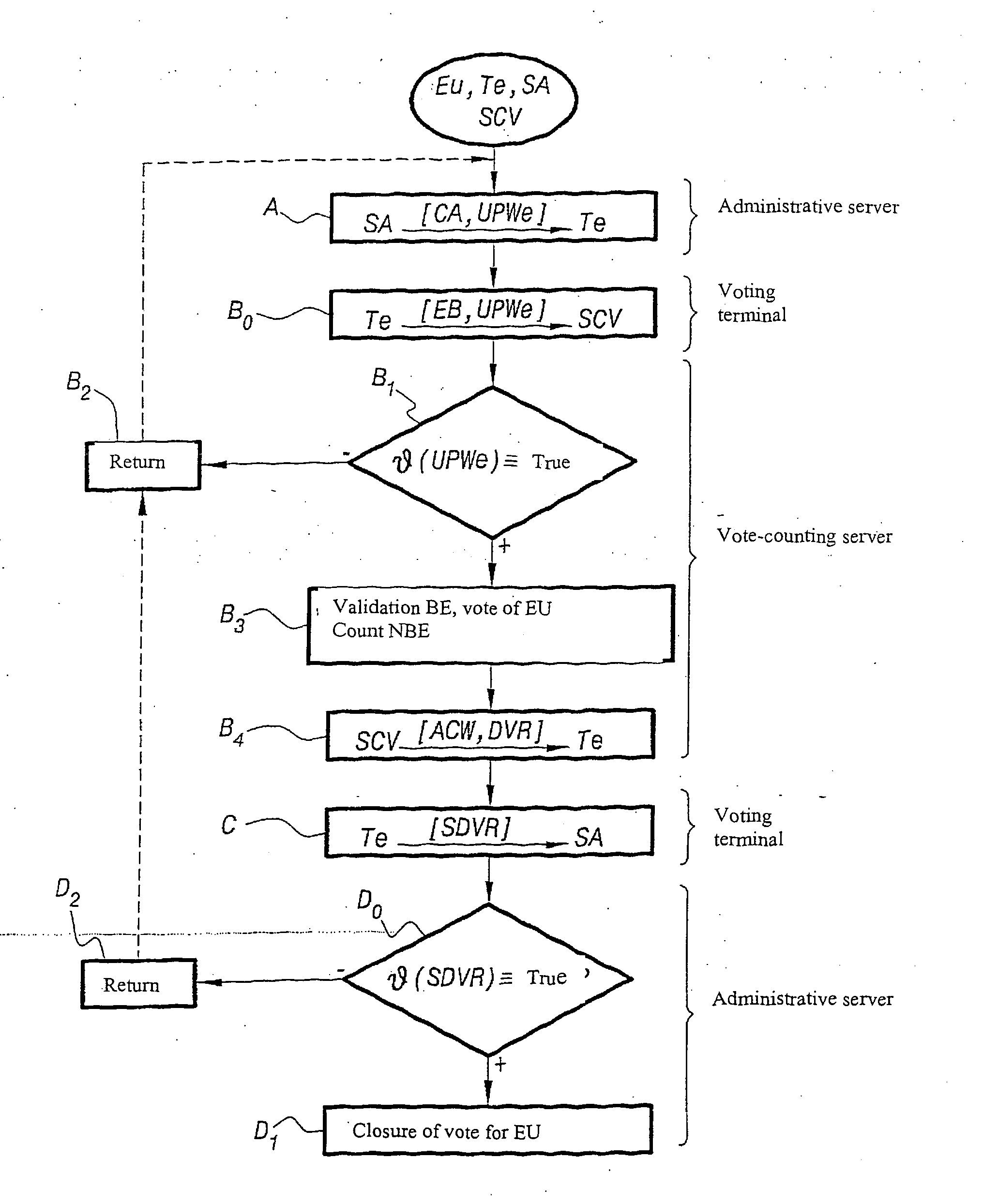
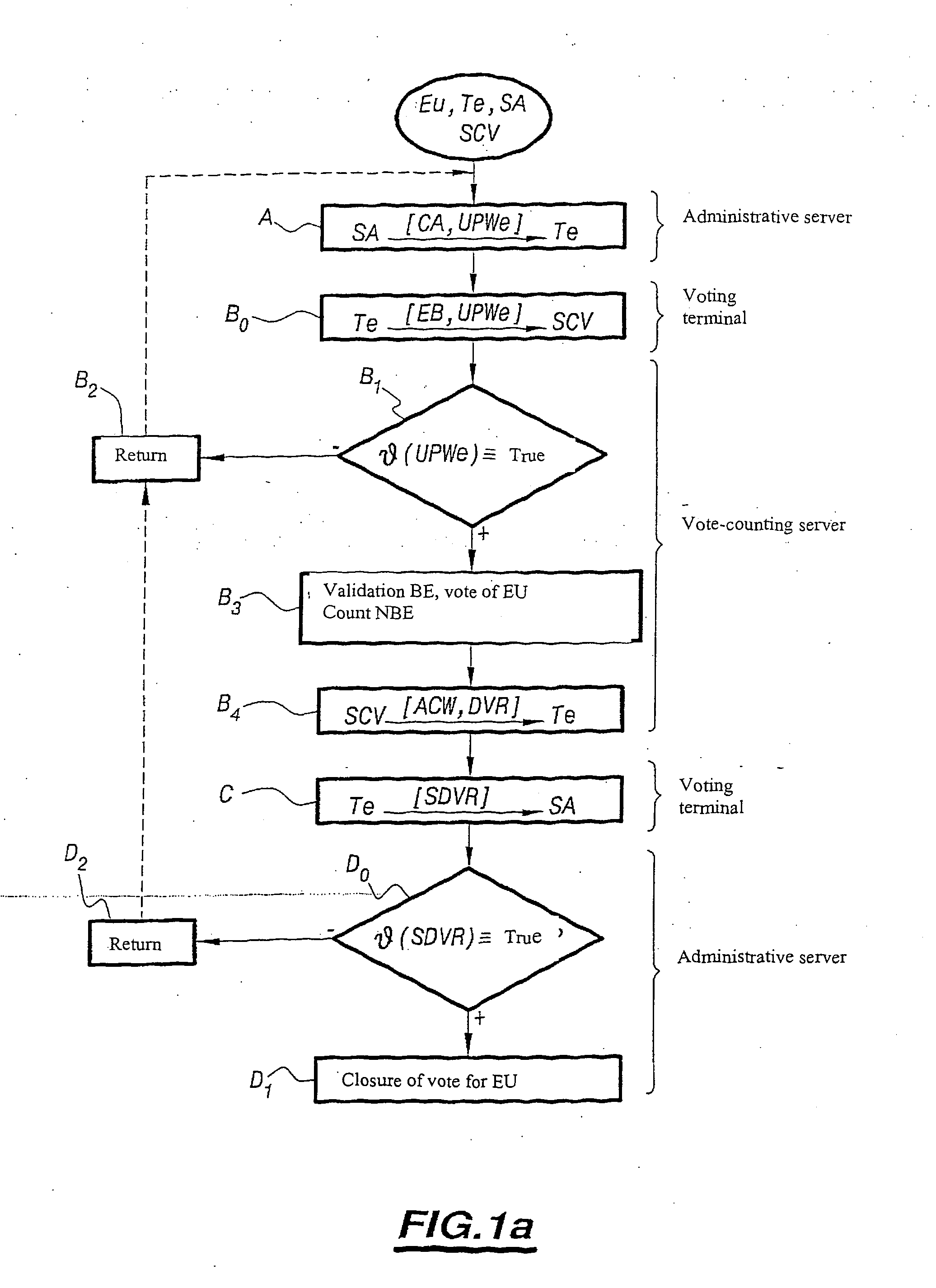
[0065] A more detailed description of the method for electronic voting over a high-security network to which the present invention relates will now be given with reference to FIG. 1a and the following Figures.

[0066] The method for electronic voting over a network, to which the present invention relates, is carried out between a voter Eu who is using a voting terminal Te connected over a network to at least one administrative server SA and a vote-counting server SCV.

[0067] Generally, it is indicated that the voting terminal Te may be constituted by various types of terminal, such as a personal computer connected to the Internet, a specific booth which is installed in a polling station and which is connected to the Internet or a booth in any public place which is also connected to the Internet and in particular to the administrative server SA and the vote-counting server SCV mentioned above, as will be described further in the description.

[0068] According to one remarkable aspect o...


PUM


Abstract

A method and system for electronic voting over a network, from a terminal (Te) connected to an administrative server (SA) and to a vote-counting server (SCV). An authentication certificate (CA) and a single-use password (UPWe) are calculated and transmitted (A) from the server (SA) to the voter (Eu), an electronic ballot paper (EB) and an anonymous reference (AREu) are transmitted (B) from the terminal (Te) to the server (SCV) and, upon verification (B1) of the anonymous reference, the vote and the paper are validated (B3), the paper is counted, a confirmation of receipt (ACW) and an electoral register document (DVR) are transmitted from the server (SCV) to the terminal (Te). The terminal (Te) signs the register and transmits (C) the signed register (SDVR) to the server (SA) which closes (D1) the vote of the voter (Eu).

Description

TECHNICAL FIELD [0001] The invention relates to a method and a system for electronic voting over a high-security network. BACKGROUND TO THE INVENTION [0002] Methods and systems for automated voting have been the subject of in-depth studies owing to the psychological, human and political implications which are associated therewith and the technical solutions which allow the problems presented thereby to be overcome. [0003] According to a first type of these methods and systems, the identity of the voter casting his vote is manually controlled. This control affords access to the electronic voting system which then simply has to control the routing of an electronic ballot paper in a reliable manner to a vote counting machine. [0004] A first type mentioned above substantially corresponds to that described by U.S. patent application U.S. 2003208395 in which an electronic ballot paper, constituted, for example, by a mini-application (“applet”), is loaded by the voter casting his vote onto...

Claims


Application Information

Patent Timeline
IPC IPC(8): G06F17/60G07C13/00H04L9/32
CPCH04L9/3257H04L2209/466H04L2209/42H04L9/3263G06Q50/26
Inventor VERNAY, FRANCOISTRAORE, JACQUESBONAMOUR, ANTOINE
Owner FRANCE TELECOM SA
Why Eureka
Try Eureka