Apparatus for acquiring an image of a predetermined extract of a moving printed product

a technology of printed products and extracts, applied in the field of apparatus for acquiring images of predetermined extracts of moving printed products, can solve the problems of high cost, inability to meet the needs of users, and inability to achieve the effects of reducing the number of images, high packing density, and high degree of redundancy

Active Publication Date: 2006-01-05
GRAPHO METRONIC MESS UND REGELTECHN GMBH & CO
View PDF10 Cites 11 Cited by
  • Summary
  • Abstract
  • Description
  • Claims
  • Application Information

AI Technical Summary

Benefits of technology

[0014] Because of their small dimensions, light-emitting diodes (LEDs) are particularly well-suited as light sources to achieve a high packing density, which allows a high level of mutual overlapping of the individual radiation cones of the light sources. This provides a high degree of redundancy and therefore security against failure, as well as homogeneous and intensive illumination of the area of observation of the camera. In addition to conventional light-emitting diodes, laser diodes are also suitable as light sources. Furthermore, gas discharge lamps and halogen incandescent lamps are in principle also suitable as light sources, and it is possible for halogen light sources to be used with a shutter in the camera to implement sufficiently short illumination times.
[0015] By using imaging optics for focusing the light from the light sources onto the area of observation of the camera, the working distance between the illumination device and the printed product can be increased. This is of interest in particular for application of inline measurement in sheet-fed presses, since a relatively large working distance is necessary there because of the type of movement of the printing material. Given an elongated arrangement of the light sources in the form of rows, cylindrical lenses are recommended in order to save effort in implementing the imaging optics. For a large number of light sources, only a single cylindrical lens or possibly a few cylindrical lenses in series are needed in the beam path. The lens or lenses should extend for a sufficient distance in the direction of the longest dimension of the arrangement of light sources, which in the case of a row is the longitudinal direction of the row. The number of different optical components which have to be adjusted in relation to each other therefore remains small.
[0016] A modular combination of a plurality of illumination devices may be made to form a larger illumination unit. To that end, it is advantageous if the housings of the individual illumination devices and the holders of their optical components are configured in such a way that when illumination devices of the same type are lined up laterally in a row the optical components of the individual illumination devices adjoin one another without any significant gaps. This includes, for example, configuring the housing and the holder of the imaging optics so that they do not interfere with or even block the light entry and exit from a possible adjacent module, in order not to interrupt the overlapping of the cones of light from the light sources in the transition region. Also, side walls of the housing should be designed to be sufficiently thin or removable, so that the suitable spacing of the light sources can be maintained even in the transition region. In the case of a periodic arrangement of light sources, this means that the periodicity is preserved in the transition region.
[0017] To acquire an image of a narrow control strip, which extends over virtually the entire width of a printed product and transversely with respect to its direction of motion, it is convenient to line up camera modules linearly in a row so that their areas of observation are adjoining one another either without any gaps or overlapping slightly, so as to result in an overall coherent area of observation. The entire area of observation of such a combined camera arrangement can be conveniently illuminated using an appropriate combination of modular illumination devices that likewise adjoin one another without any significant gaps. To preserve the homogeneity of the illumination along the entire area of observation of the camera arrangement, it is necessary for the patterns of the light sources of different colors of each illumination device to be continued without disruption by being lined up in a row. In the case of a periodic pattern, this means continuing the periodicity. Furthermore, in this case, synchronous activation of the individual illumination devices is necessary, that is to say all the light sources of a spectral group in all the illumination devices have to be switched on and off at the same time. Lining up identical illumination devices modularly in a row to form a larger unit does not necessarily assume a corresponding modular camera arrangement, however. Instead, it can also be useful for illuminating the area of observation of a single camera, if the latter has a sufficiently great length.

Problems solved by technology

Color cameras of this type have a complicated structure and are accordingly costly.
In addition, they are inferior to black-and-white cameras in terms of sensitivity.
Furthermore, each color camera has a predefined spectral sensitivity characteristic, which cannot be changed from the outside.

Method used


Image

  • Apparatus for acquiring an image of a predetermined extract of a moving printed product
  • Apparatus for acquiring an image of a predetermined extract of a moving printed product
  • Apparatus for acquiring an image of a predetermined extract of a moving printed product

Examples


Embodiment Construction

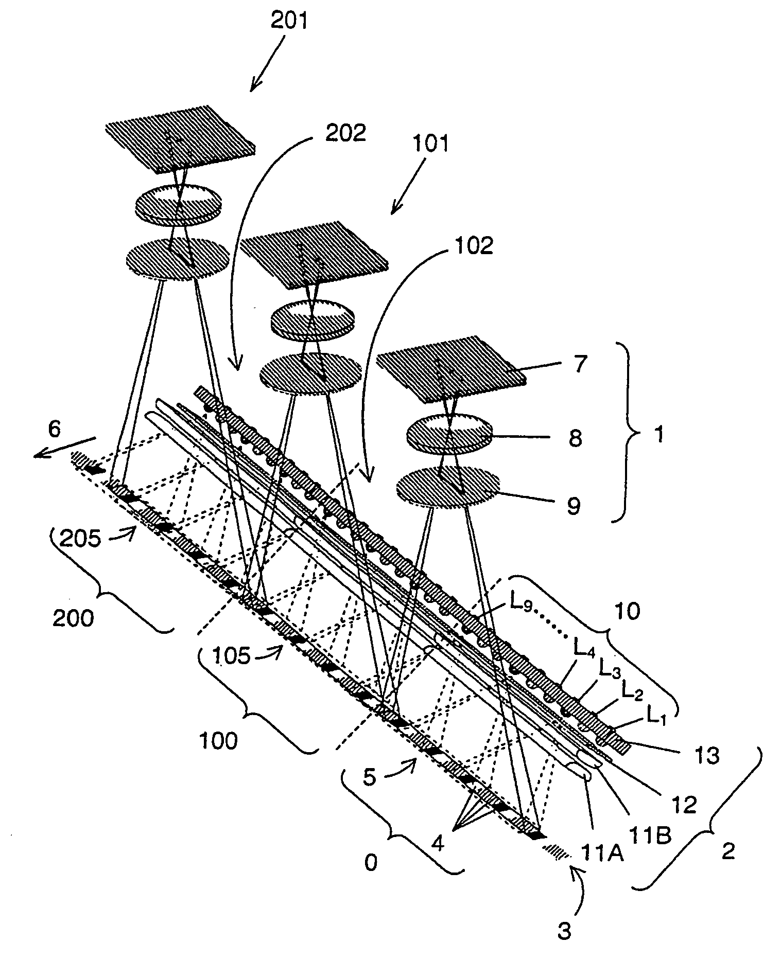
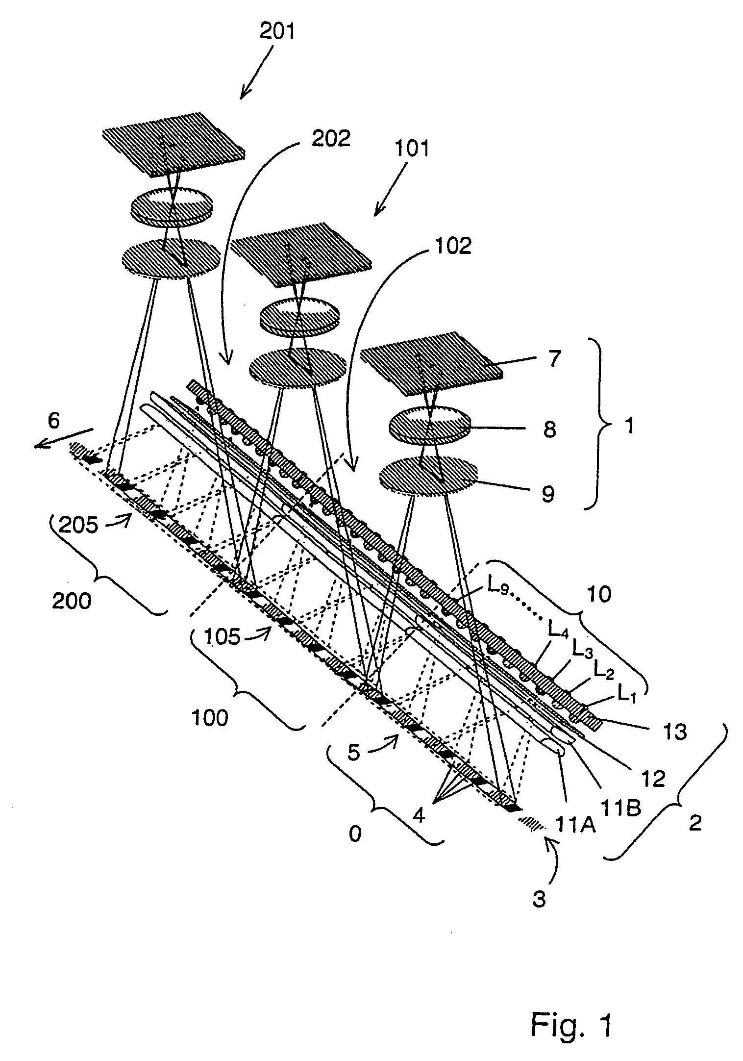
[0027]FIG. 1 shows in a simplified form the optical components of a preferred embodiment of the apparatus according to the invention, namely an electronic camera 1 and an associated illumination device 2. In this case, a plurality of identical cameras 1, 101 and 201 and a plurality of illumination devices 2, 102 and 202, respectively, assigned thereto are lined up modularly in a row. This possibility of combining a plurality of modules 0, 100 and 200, each comprising a camera and an illumination device, to form a larger unit is a particularly advantageous property of the invention. Initially, however, the construction of a single module and its functioning will be explained by using the module 0, which comprises the camera 1 and the illumination device 2.

[0028] The camera 1 is intended to record an image from a predetermined extract of a printed product, for example from a control strip 3 having a large number of periodically repeating measurement areas 4, while the control strip 3...


PUM


Abstract

An apparatus and method for acquiring an image of a predetermined extract of a moving printed product employs at least one black-and-white camera with a two-dimensional electronic image sensor and one or more illumination devices suitable for pulse-like illumination. The illumination device has multiple light sources forming spectral groups that have different spectral compositions. The light sources are arranged in a pattern such that the light sources of each spectral group completely illuminate the area of observation of the camera. A control device switches the individual spectral groups of light sources on and off sequentially such that the area of observation of the camera is illuminated with a sequence of light pulses of different spectral compositions. During each light pulse, the predetermined extract on a printed product moves into the area of observation of the camera, and an image of extract is captured.

Description

FIELD OF THE INVENTION [0001] The invention relates to an apparatus for acquiring an image of a predetermined extract of a moving printed product, and to a method of operating such an apparatus. BACKGROUND OF THE INVENTION [0002] For the purpose of process monitoring during printing, it is usual to provide printed control strips with colored test patterns outside the subject on sheets or webs to be printed. These control strips, whose longitudinal direction is transverse with respect to the transport direction of the printing material, contain a set of measurement areas which repeat periodically in the longitudinal direction, on each of which a specific characteristic variable that characterizes the printing quality can be measured. An image of at least part of the control strip is acquired and evaluated during the movement of the printed product to be examined in the press. As an alternative to a control strip provided specifically for the purpose, in principle a portion of the pri...

Claims


Application Information

Patent Timeline
Patent Type & Authority Applications(United States)
IPC IPC(8): H04N1/46B41F33/14B41F33/00B41F33/10G01J1/20G01J3/46G03B15/02G06T1/00H04N1/00H04N1/19H04N9/04
CPCB41F33/0036
Inventor TATARCZYK, THEODOR
Owner GRAPHO METRONIC MESS UND REGELTECHN GMBH & CO
Why Eureka
Try Eureka