Crystal detection with scattered-light illumination and autofocus

a technology of autofocus and crystal detection, applied in the field of optical microscopes, can solve the problems of noisy images, large loss of light, and substantially greater illumination intensities,

Inactive Publication Date: 2006-01-05
WAHL MICHAEL +1
View PDF4 Cites 26 Cited by
  • Summary
  • Abstract
  • Description
  • Claims
  • Application Information

AI Technical Summary

Benefits of technology

[0012] According to another embodiment of the invention, a strobed arc-lamp source is used for image acquisition and a separate source, potentially a laser, is used for autofocus purposes and is kept on continuously as the sample tray is being scanned. When the scatter shutter is not energized, the laser beam produces the optical signals off the underside of the tray required to adjust the focal position

Problems solved by technology

As illustrated in FIG. 1, the problem with this approach is the fact that the small amount of liquid in each well 10 of a multi-well plate, as a result of the surface tension of the liquid, forms a droplet 12 with a top curvature that makes the drop equivalent to an optical lens.
This enhances edges within the field, but much of the light is lost and substantially greater intensities of illumination need to be used.
Otherwise, noisy images are produced.
As is well understood in the art, dark-field illumination also does not work well when there is a significant separation of the sample fro

Method used


Image

  • Crystal detection with scattered-light illumination and autofocus
  • Crystal detection with scattered-light illumination and autofocus
  • Crystal detection with scattered-light illumination and autofocus

Examples


Embodiment Construction

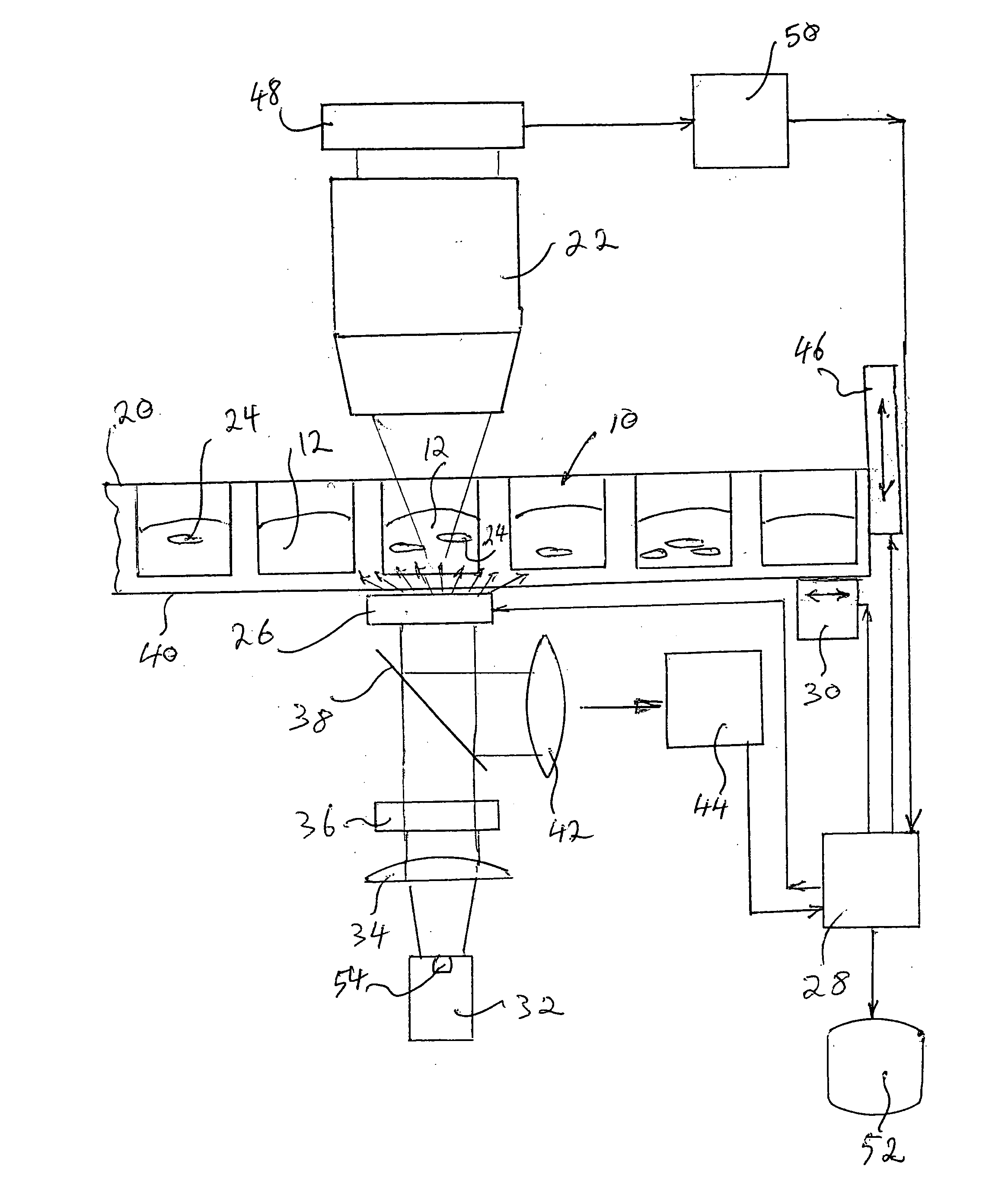
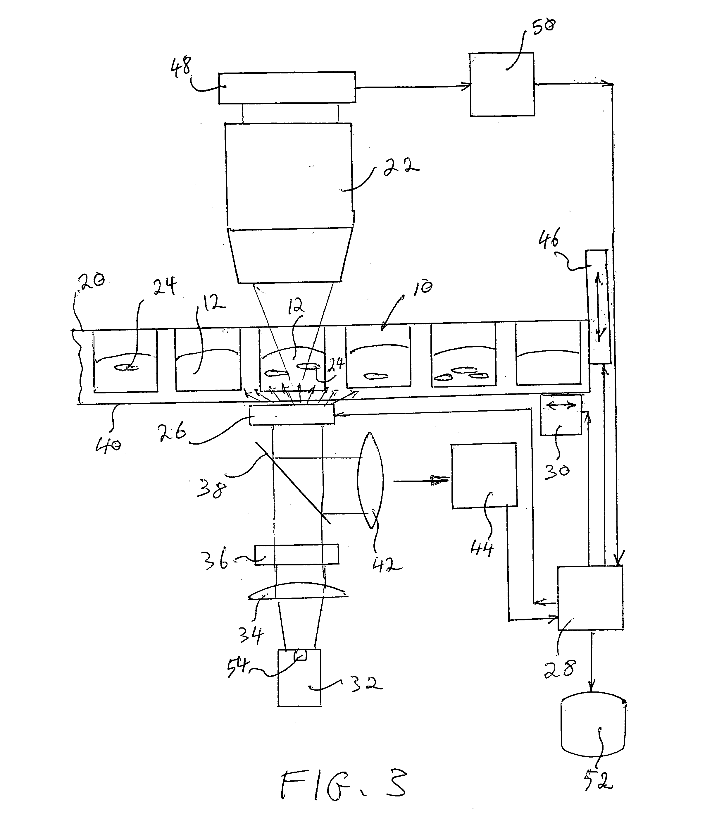
[0019] The inventive aspect of this disclosure lies in the idea of using an intermittent scatter plate in the optical axis of illumination of a microscope used for high-throughput testing of multi-well trays. The intermittent light-scatter function provided by the plate allows the alternate bright-field illumination required for the operation of conventional autofocusing mechanisms and the scatter-light illumination required for uniform imaging of the entire well. In addition, the fact that both modes of illumination may be implemented from the same side of the sample tray provides construction, maintenance and operational advantages over prior-art microscope systems used for rapid sample screening.

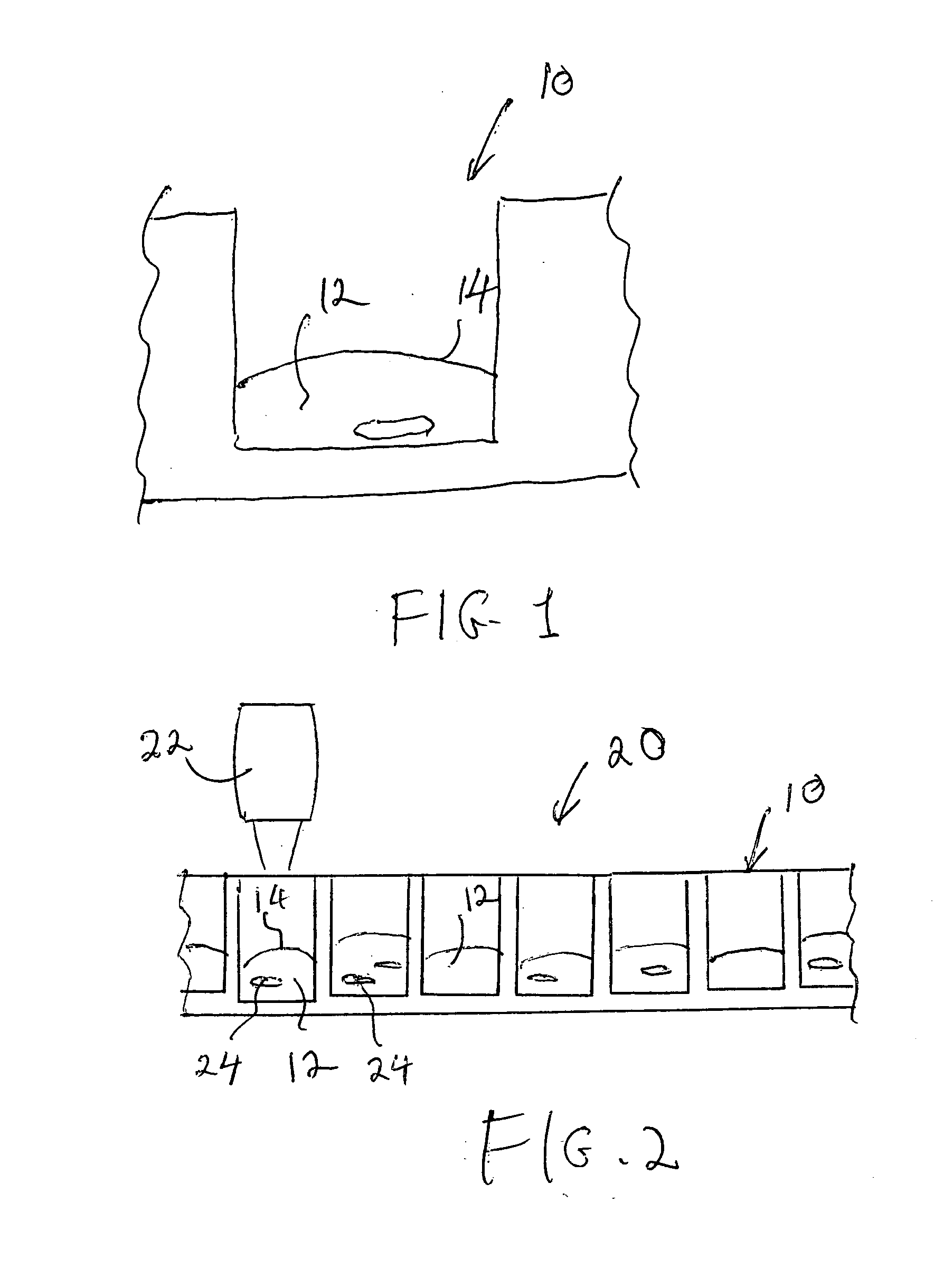
[0020] Referring to the drawings, wherein like parts are designated throughout with like numerals and symbols, FIG. 2 illustrates in schematic cross-sectional view a multi-well plate 20 used to carry out high-throughput screening of protein crystal samples according to the invention. Eac...


PUM


Abstract

A scatter shutter is used to alternately provide non-scattered illumination for autofocus purposes and diffuse illumination for imaging purposes in a microscope system for high-throughput testing of protein samples in a multi-well tray. As the tray is being scanned continuously through the microscope objective for data acquisition, the scatter shutter is intermittently deactivated to allow collimated light to focus on the underside of the tray and produce autofocus signals, and then activated to produce diffused light and to image the protein sample in each well. The timing of each step is synchronized so as to place the droplet in focus prior to energizing the scatter shutter and switching to the imaging mode.

Description

BACKGROUND OF THE INVENTION [0001] 1. Field of the Invention [0002] This invention is related in general to equipment and processes for high-throughout screening of biological samples. In particular, the invention consists of an optical microscope for detecting the formation of protein crystals in liquid droplets contained in a multi-well tray that is rapidly scanned through the microscope objective. [0003] 2. Description of the Related Art [0004] In fast-throughput screening of biological samples, individual samples are loaded into separate wells of multi-well trays or plates, where they are treated with reagents (or otherwise processed) and screened for target results. In the case of proteins, they are typically crystallized out of a liquor and analyzed for molecular structure using X-ray diffraction techniques. For fast throughput, the protein solution is loaded as a droplet into each well of such a multi-well tray (typically a 96-well plate) and is processed through an incubatio...

Claims


Application Information

Patent Timeline
IPC IPC(8): G02B21/00
CPCG02B21/086G02B26/00G02B21/241
Inventor WAHL, MICHAELNOVAK, ERIK L.
Owner WAHL MICHAEL
Why Eureka
Try Eureka