Volumetric computed tomography (VCT)

a computed tomography and volumetric technology, applied in the field of ct systems, can solve the problems of obstructing visibility, inability to know, and multi-detector or multi-row ct systems still need more than one revolution during image scanning, and achieve the effect of fast and reliabl

Inactive Publication Date: 2006-01-05
THE BOARD OF TRUSTEES OF THE LELAND STANFORD JUNIOR UNIV
View PDF1 Cites 43 Cited by
  • Summary
  • Abstract
  • Description
  • Claims
  • Application Information

AI Technical Summary

Benefits of technology

[0011] Accordingly, it is a primary object of the present invention to provide a fast and reliable volumetric CT system capable of providing image data for reconstructing an entire 3D object using a single rotation without suffering from image artifacts such as cone beam artifacts, overcoming image reconstruction errors and beam divergence problems common in known cone-beam CT systems.

Problems solved by technology

While these images can be very useful, when there is one structure in front or behind another, their images are superimposed in a single projection image and it is impossible to know which is in front, and each may obstruct the visibility of the other.
However, these multi-detector or multi-row CT systems still require more than one revolution during image scanning to produce data for a thick volume.
Unfortunately, this imaging geometry suffers from several known drawbacks such as image artifacts, sometimes referred to as cone beam artifacts, and image reconstruction errors.
Briefly, the divergence of the x-ray beam in the direction of the axis of rotation causes the reconstruction problem to be ill-posed.
Indeed, even in multi-row CT systems, as the angle spanned by the multiple rows increases, so do the image reconstruction problems caused by the image artifacts.
As such, the system will increasingly suffer from cone beam artifacts.
Additionally, if one tries to reduce these artifacts by using more accurate reconstruction algorithms, image reconstruction can be computationally intensive and slow in cone beam CT systems.

Method used


Image

  • Volumetric computed tomography (VCT)
  • Volumetric computed tomography (VCT)
  • Volumetric computed tomography (VCT)

Examples


Embodiment Construction

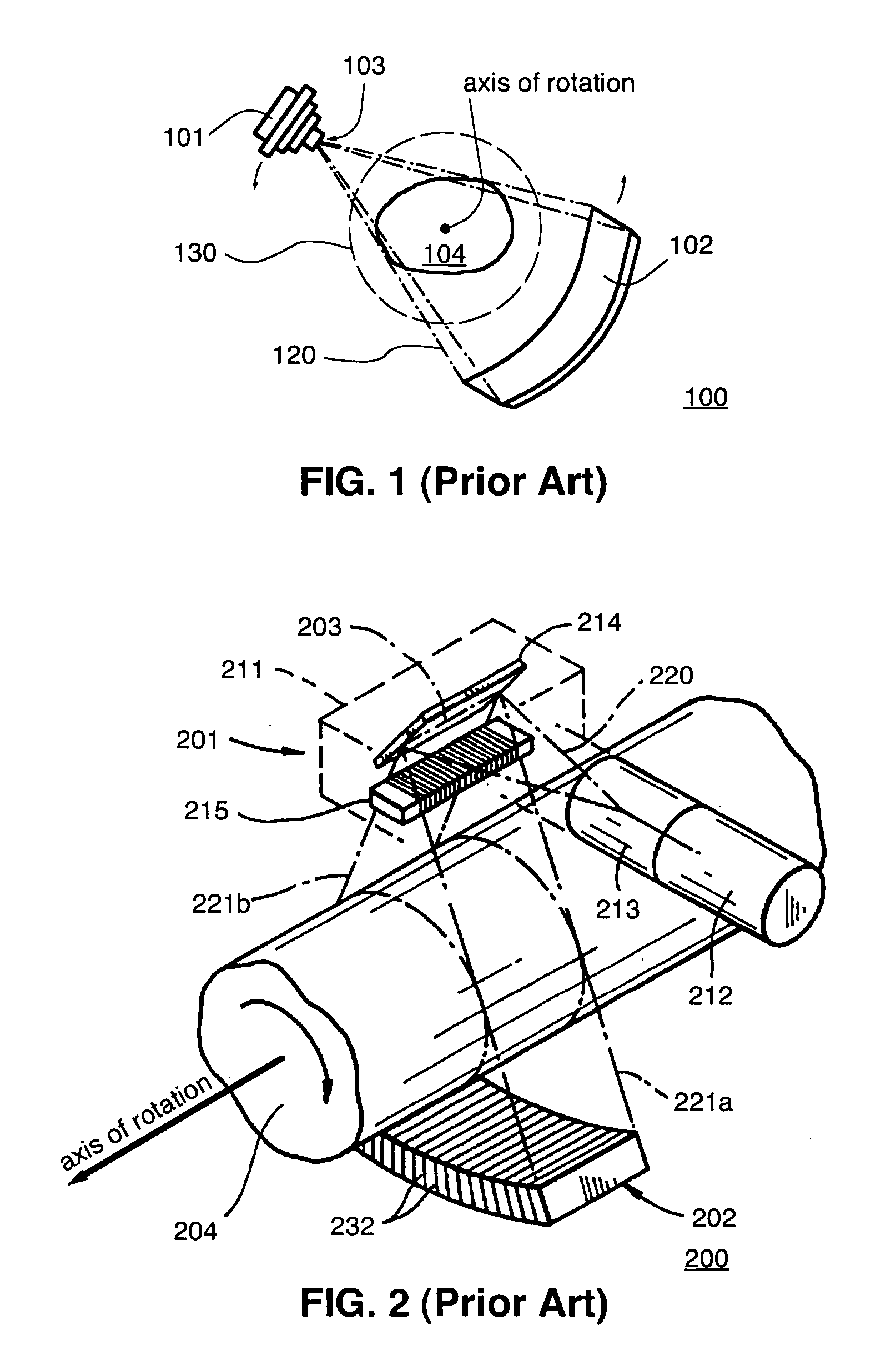
[0019]FIG. 1 illustrates a prior art cone beam CT system 100. System 100 includes an x-ray source 101, which employs an x-ray tube, for providing x-rays 120 emanating from a point 103, hereinafter referred to as the focal spot 103. The detector array 102 can be a wide arc or a flat 2-dimensional array containing dozens or hundreds of rows of x-ray detectors. Detector 102 measures x-rays emanating in all directions from the focal spot 103. The cone beam CT system 100 is characterized by the shape of x rays 120 emanated from the focal spot 103 onto the detector array 102. Both the x-ray source 101 and the detector array 102 may be mounted on a gantry (not shown), and may revolve around an axis of rotation of a circular opening 130. The gantry could be a C-arm. An object 104, typically a patient, is positioned in the circular opening 130 via an examination platform, e.g., a motorized table (not shown) that can move up or down and slide in or out of the circular opening 130, so as to pl...


PUM

PropertyMeasurementUnit
thicknessaaaaaaaaaa
thicknessaaaaaaaaaa
angleaaaaaaaaaa

Abstract

The present invention provides a volumetric computed tomography (VCT) system capable of producing data for reconstructing an entire three-dimensional (3D) image of a subject during a single rotation without suffering from cone beam artifacts. The VCT system comprises an array of source positions distributed along a line parallel to an axis of rotation, a plurality of collimators, and an array of x-ray detectors. In a preferred embodiment, a reversed imaging geometry is used. A 2D array of source positions provides x-rays emanating from each focal spot toward an array of detectors. The x-rays are restricted by a collimator array and measured by a detector array separately per each source position. The axial extent of the source array and the detector array are comparable to or larger than the axial extent of the portion of the object being imaged.

Description

CROSS-REFERENCE TO RELATED APPLICATIONS [0001] This application is a continuation in part of U.S. patent application Ser. No. 10 / 226,096 filed on Aug. 22, 2002, which claims the benefit of U.S. Provisional Application No. 60 / 314,943, filed Aug. 24, 2001.FIELD OF THE INVENTION [0002] The present invention relates generally to computed tomography (CT) systems and, more particularly, to volumetric CT (VCT) systems. BACKGROUND OF THE INVENTION [0003] Conventional x-ray imaging is based on the absorption of x rays as they pass through different parts of a patient's body. Depending on the absorption in a particular tissue such as muscle or lung, a different intensity of x rays will pass through and exit the body. During conventional x-ray imaging, the exiting or transmitted x rays are recorded with a detection device, such as an x-ray film or other image receptor, and provide a two dimensional projection image of the tissue within the patient's body. While these images can be very useful,...

Claims


Application Information

Patent Timeline
Patent Type & Authority Applications(United States)
IPC IPC(8): A61B6/00G01N23/00A61B6/03
CPCA61B6/032A61B6/466A61B6/4085A61B6/4028A61B6/03A61B6/06A61B6/4007A61B6/5205
Inventor PELC, NORBERT J.
Owner THE BOARD OF TRUSTEES OF THE LELAND STANFORD JUNIOR UNIV
Why Eureka
Try Eureka