Porous metallic scaffold for tissue ingrowth

a technology of metallic scaffolds and tissue ingrowth, which is applied in the direction of prosthesis, impression caps, osteosynthesis devices, etc., can solve the problems of high undesirable replacement of implants, limited range of motion, and deterioration of human bone structure, and achieves the effect of reducing the risk of fracture, and reducing the range of motion

Inactive Publication Date: 2006-01-05
HOWMEDICA OSTEONICS CORP
View PDF56 Cites 42 Cited by
  • Summary
  • Abstract
  • Description
  • Claims
  • Application Information

AI Technical Summary

Benefits of technology

[0018] Various aspects of the present invention address this need. Thus, in accordance with one aspect, the invention provides a porous metal scaffold for use in an implantable medical device comprising a porous metal network having pores defined by metal webs, the metal webs covered with at least one layer of metal particles bonded to the

Problems solved by technology

The use of orthopedic implants is the result of deterioration of human bone structure, usually because of various degenerative diseases, such as osteoarthritis.
A breakdown of a permanently installed implant leads to pain, limitation on the range of motion, and may require a replacement of the implant.
It is especially important since installation of an orthopedic implant often involves extensive and difficult medical procedure, and therefore replacement of

Method used


Image

  • Porous metallic scaffold for tissue ingrowth
  • Porous metallic scaffold for tissue ingrowth
  • Porous metallic scaffold for tissue ingrowth

Examples


example 1

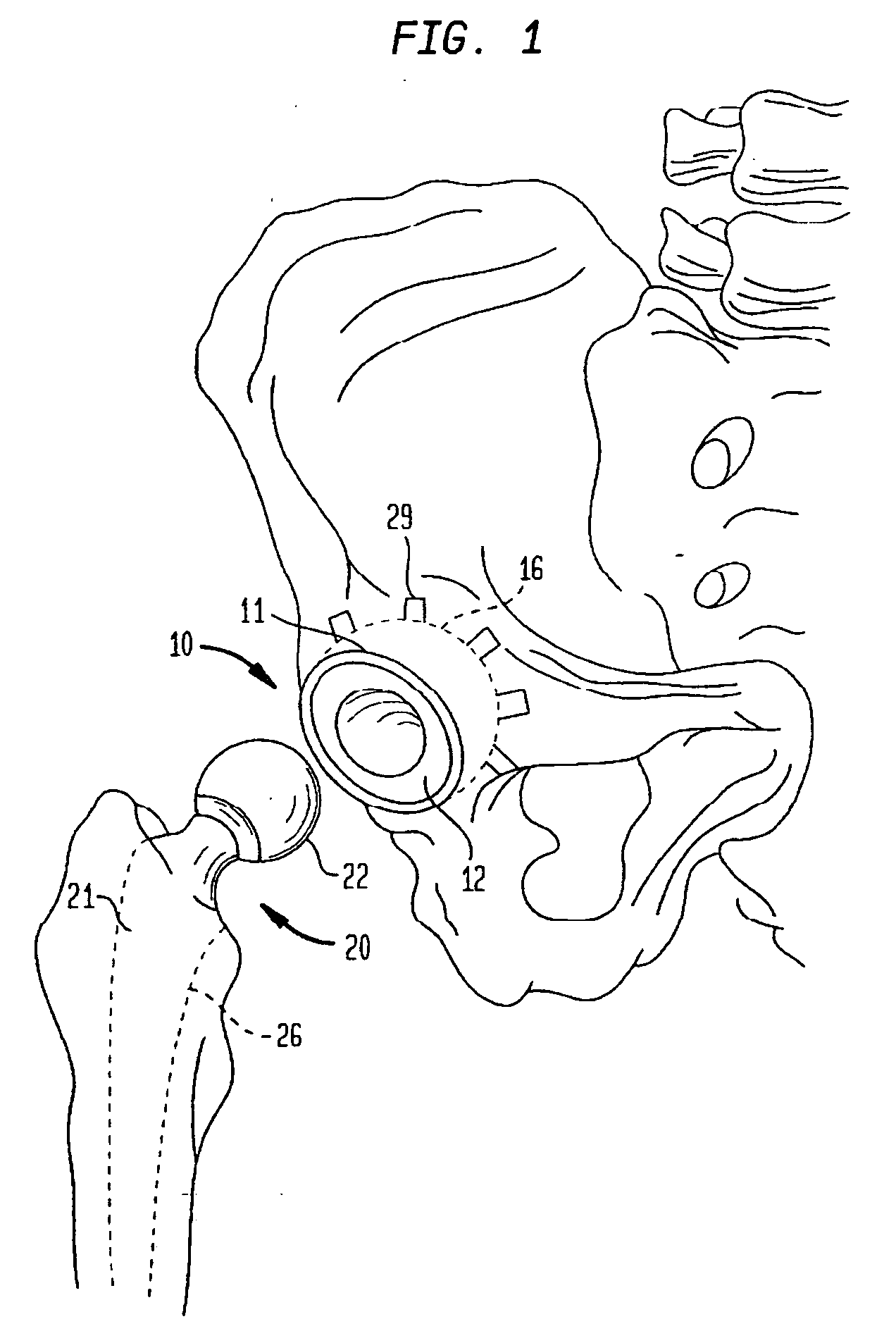
Preparation of an Acetabular Cup Implant

[0124] It should be understood that while an acetabular cup implant is illustrated, this should not be considered a limitation on the scope of the invention.

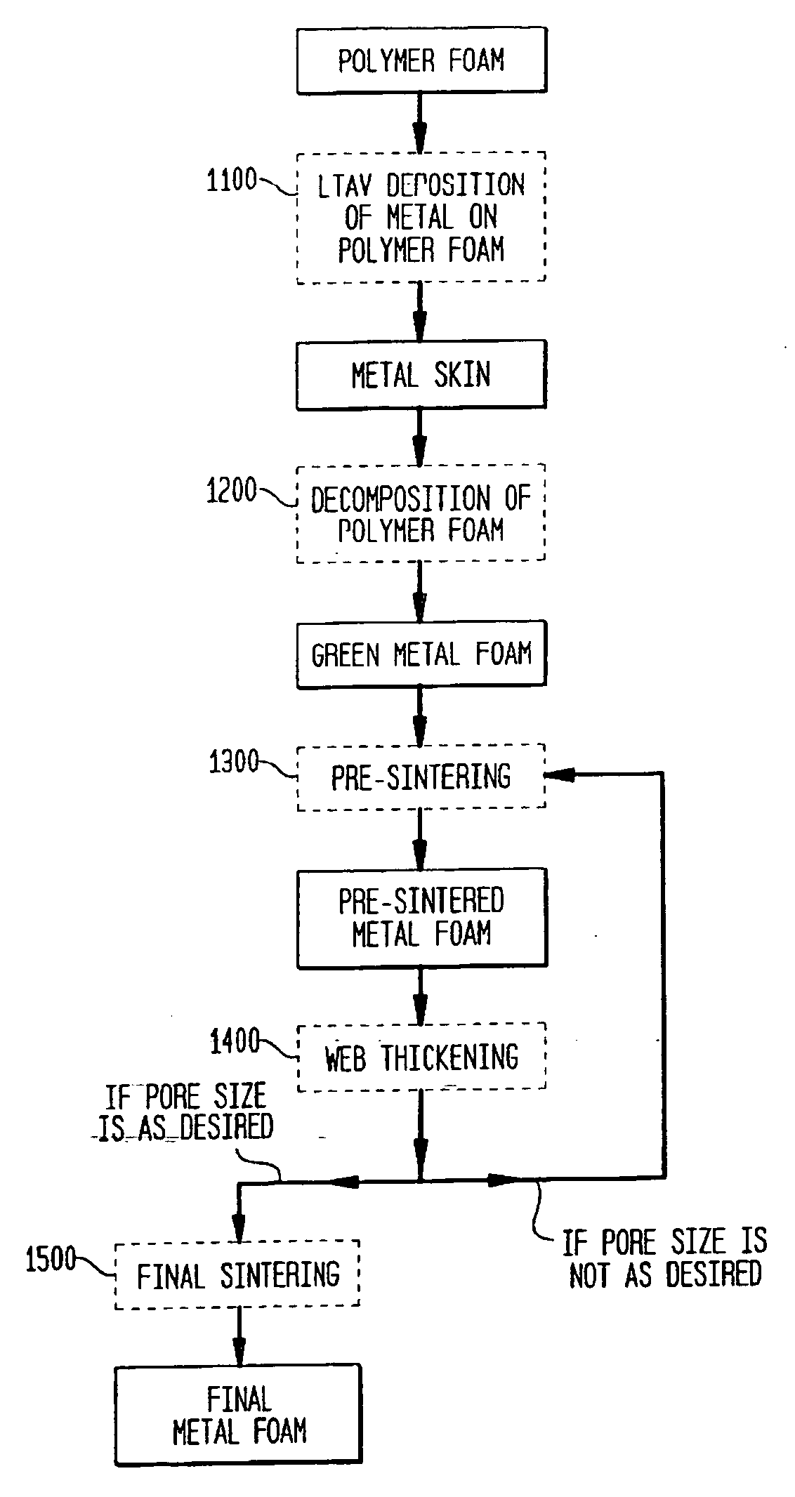
[0125] A. Formation of Green Foam.

[0126] A block of polyurethane (PU) foam (Foamex, 950 μm, 58±2 ppi) is machined to a thickness of 1.5 mm and desired size and shape matching a shell of an acetabular cup. The resulting PU foam shell is slightly oversize (˜3%) with respect to the size of the shell of the acetabular cup. The PU foam shell is subjected to LTAV deposition of titanium at 93° C. The side of the PU foam shell that will face the acetabular cup shell (ID side) is subjected to deposition for approximately 53 hours, whereas the deposition of titanium on the other side of the PU foam shell (OD side) is carried out for approximately 15 hours. The deposition is concluded when the thickness of the titanium coating reaches approximately 35 μm on the ID side and approximately 10 μm on t...

example 2

[0133] The shell is processed as in the Example 1, but instead of the two powder treatments, the foam is thickened by vapor deposition (e.g., LTAVD, PVD, or CVD) of titanium until a 150-200 μm layer is deposited.

example 3

[0134] The shell is processed as in the Example 1, but the pore size of the polyurethane foam is 924 μm±89 μm, the pore size of the green foam after LTAV deposition is 967 μm±82 μm, and the pore size of the final foam is 614 μm±67 μm.


PUM

PropertyMeasurementUnit
Lengthaaaaaaaaaa
Lengthaaaaaaaaaa
Fractionaaaaaaaaaa

Abstract

The invention relates to implantable medical devices, particularly, to porous structures for such devices. In one aspect, the invention provides a porous metal scaffold comprising a porous metal network having pores defined by metal webs, the metal webs covered with at least one layer of metal particles bonded to the metal webs. In other aspects, the invention provides methods of forming porous scaffolds. In one such aspect, the method includes providing a polymer foam; forming a skin of biocompatible metal on the polymer foam by low temperature arc vapor deposition; and heating the polymer foam and the metal skin above the decomposition temperature of the polymer foam in an inert gas atmosphere; thereby the polymer foam decomposes producing a green metal foam. In yet other aspects, the invention provides methods of improving stability of porous scaffolds.

Description

CROSS-REFERENCE TO RELATED APPLICATIONS [0001] This application is a divisional of U.S. application Ser. No. 10 / 071,667, filed on Feb. 8, 2002, the disclosure of which is incorporated herein by reference.FIELD OF THE INVENTION [0002] The present invention relates to implantable medical devices, and in particular to porous scaffolds for implantable medical devices, especially orthopedic implants, methods of forming such scaffolds, and methods of producing such devices. BACKGROUND OF THE INVENTION [0003] The use of orthopedic implants is the result of deterioration of human bone structure, usually because of various degenerative diseases, such as osteoarthritis. In recent years, a variety of implantable orthopedic devices had been developed. Typically, the failed bone structure is replaced with an orthopedic implant that mimics the structure of the natural bone and performs its functions. [0004] Orthopedic implants are constructed from materials that are stable in biological environme...

Claims


Application Information

Patent Timeline
IPC IPC(8): B32B5/18A61F2/28B05D3/10A61B17/68A61B17/86A61F2/00A61F2/30A61F2/32A61F2/34A61F2/36A61F2/46A61L27/30A61L27/40A61L27/56B22F3/11B22F7/00
CPCA61B17/68Y10T428/12479A61F2/30767A61F2/3094A61F2/32A61F2/34A61F2/36A61F2/3662A61F2/4657A61F2002/30011A61F2002/3092A61F2002/30929A61F2002/30968A61F2002/3098A61F2002/3611A61F2002/4631A61F2250/0023A61F2310/00023A61F2310/00029A61F2310/00095A61F2310/00131A61F2310/00407A61F2310/00413A61F2310/00491A61F2310/00544A61L27/30A61L27/40A61L27/56B22F3/1137B22F3/114B22F7/004B22F2999/00A61B17/86
Inventor WANG, KATHY K.DONG, NICHOLAS NAI GUANGMEEHAN, MICHAEL
Owner HOWMEDICA OSTEONICS CORP
Why Eureka
Try Eureka