High sensitivity capacitive micromachined ultrasound transducer

a micro-machined, ultrasonic transducer technology, applied in the field of medical imaging systems, can solve the problem of limiting the maximum amplitude of the diaphragm displacemen

Inactive Publication Date: 2006-01-05
GENERAL ELECTRIC CO
View PDF8 Cites 107 Cited by
  • Summary
  • Abstract
  • Description
  • Claims
  • Application Information

AI Technical Summary

Problems solved by technology

However, the small cavity depth limits the maximum amplitude of the diaphragm displacement when the cMUT transceiver is used as a transmitter.

Method used


Image

  • High sensitivity capacitive micromachined ultrasound transducer
  • High sensitivity capacitive micromachined ultrasound transducer
  • High sensitivity capacitive micromachined ultrasound transducer

Examples


Embodiment Construction

[0030] In many fields, such as medical imaging and non-destructive evaluation, it may be desirable to utilize ultrasound transducers that enable the generation of high quality diagnostic images. High quality diagnostic images may be achieved by means of ultrasound transducers, such as, capacitive micromachined ultrasound transducers, that exhibit high sensitivity to low level acoustic signals at ultrasonic frequencies. The techniques discussed herein address some or all of these issues.

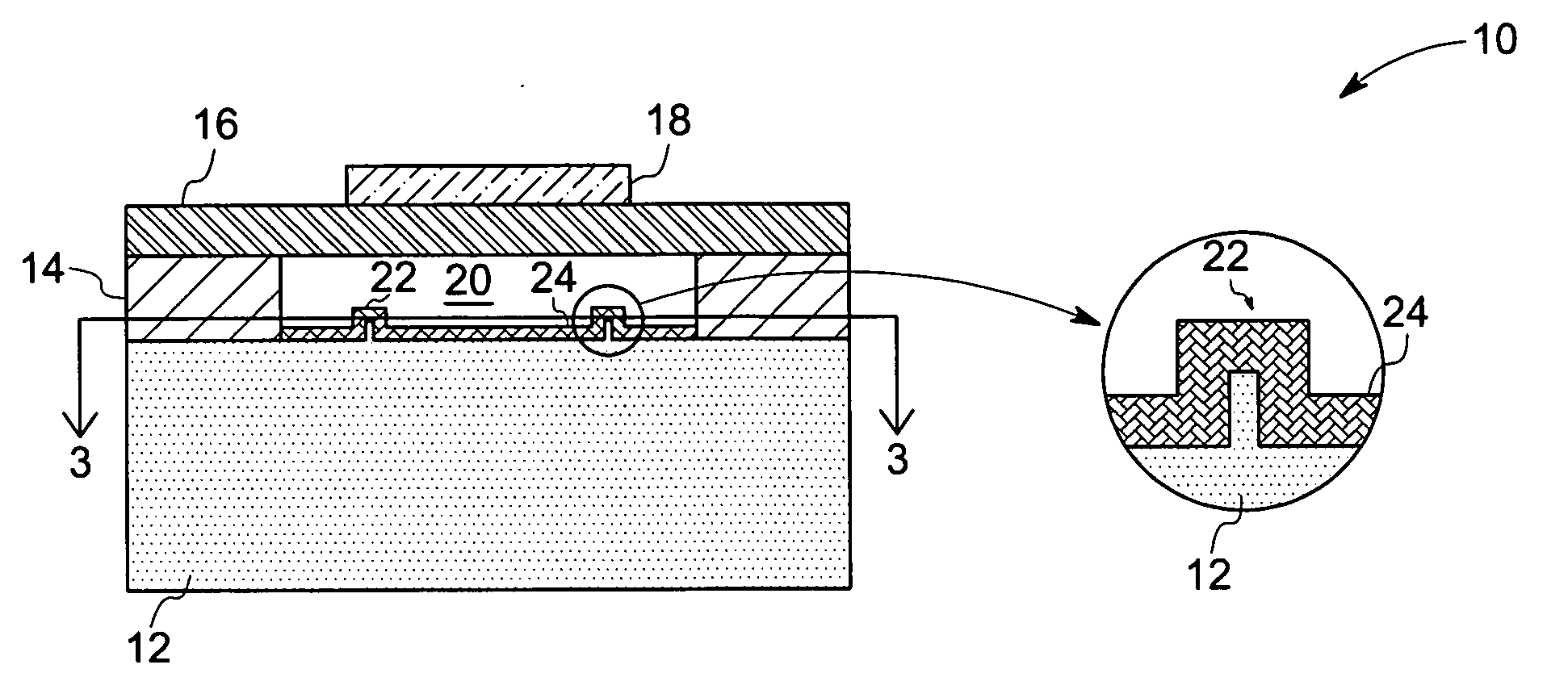
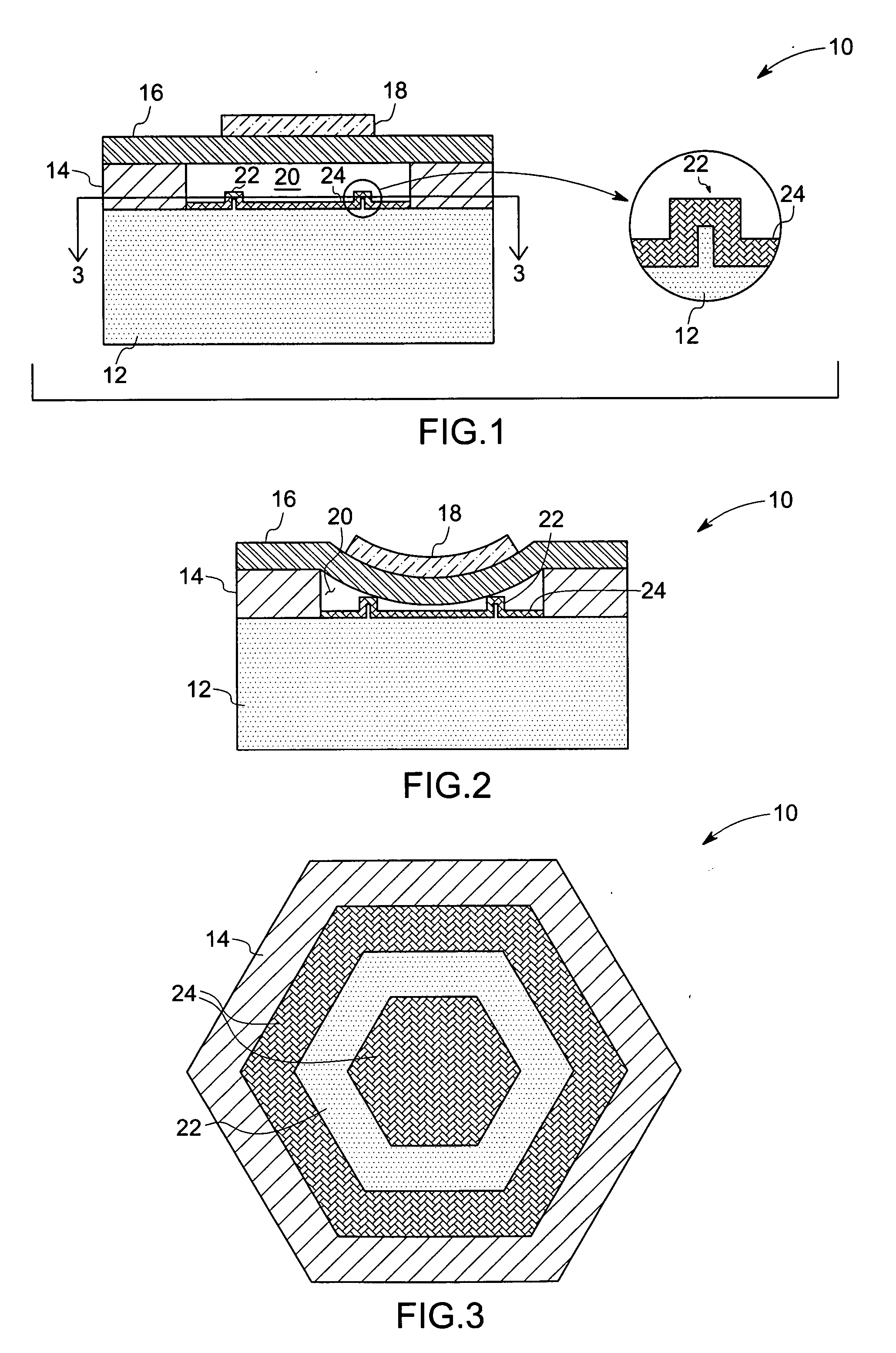
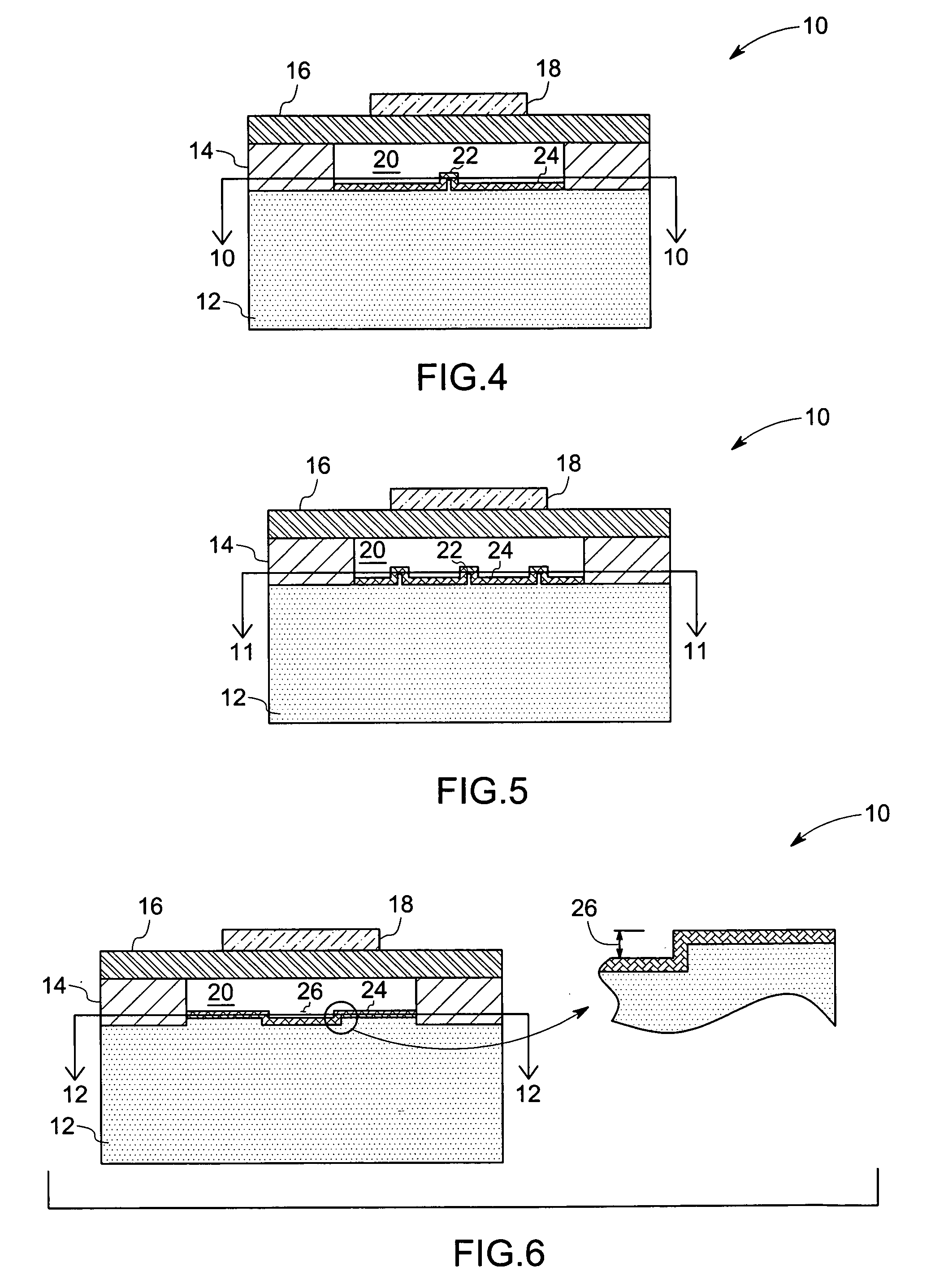
[0031] Turning now to FIG. 1, a side view of a cross-section of an embodiment of a capacitive micromachined ultrasound transducer (cMUT) transceiver 10 is illustrated. As will appreciated by one skilled in the art, the figures are for illustrative purposes and are not drawn to scale. FIG. 1 depicts the cMUT transceiver 10 operating in a transmit mode. The cMUT transceiver 10 comprises a lower electrode 12, having a topside and a bottom side, which may be disposed on a substrate (not shown). The thick...


PUM


Abstract

A capacitive micromachined ultrasound transducer (cMUT) comprises a lower electrode. Furthermore, the cMUT includes a diaphragm disposed adjacent to the lower electrode such that a gap having a first gap width is formed between the diaphragm and the lower electrode. Additionally, the cMUT includes at least one element formed in the gap, where the at least one element is arranged to provide a second gap width between the diaphragm and the lower electrode.

Description

BACKGROUND [0001] The invention relates generally to medical imaging systems, and more specifically to capacitive micromachined ultrasound transducers (cMUTs). [0002] Transducers are devices that transform input signals of one form into output signals of a different form. Commonly used transducers include light sensors, heat sensors, and acoustic sensors. An example of an acoustic sensor is an ultrasonic transducer, which may be implemented in medical imaging, non-destructive evaluation, and other applications. [0003] Currently, one form of an ultrasonic transducer is a capacitive micromachined ultrasound transducer (cMUT). A cMUT cell generally includes a substrate that contains a lower electrode, a diaphragm suspended over the substrate by means of support posts, and a metallization layer that serves as an upper electrode. The lower electrode, diaphragm, and the upper electrode define a cavity. In conventional cMUT devices, the gap between the upper and lower electrodes of the cMU...

Claims


Application Information

Patent Timeline
Patent Type & Authority Applications(United States)
IPC IPC(8): A61B8/14B81C99/00
CPCB06B2201/76B06B1/0292
Inventor TIAN, WEI-CHENGLEE, WARRENSMITH, LOWELL SCOTTLI, YE-MINGSUN, JIE
Owner GENERAL ELECTRIC CO
Why Eureka
Try Eureka