Handle for a Handheld Working Tool

Inactive Publication Date: 2006-01-12
ANDREAS STIHL AG & CO KG
View PDF13 Cites 3 Cited by
  • Summary
  • Abstract
  • Description
  • Claims
  • Application Information

AI Technical Summary

Benefits of technology

[0004] It is an object of the present invention to further develop a handle of a handheld working tool (power tool) such that in operation of the working tool a reduced vibration level occurs at the handle.

Problems solved by technology

When operating a handheld working tool (power tool), such as a motor chainsaw, a trimmer or the like, mechanical vibrations occur that can be caused by the running of a drive motor or by the driven cutting tool.
Excessive vibrations can cause the operator to experience untimely fatigue or can lead to an unsatisfactory work result.

Method used


Image

  • Handle for a Handheld Working Tool
  • Handle for a Handheld Working Tool
  • Handle for a Handheld Working Tool

Examples


Embodiment Construction

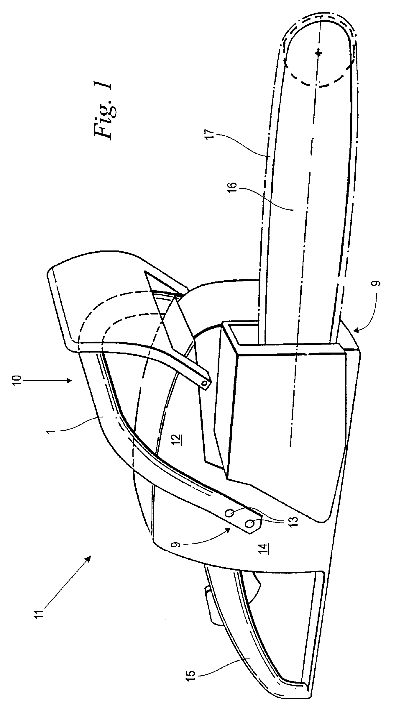
[0020]FIG. 1 shows in a perspective illustration a handheld working tool (power tool) 11 in the form of a motor chainsaw. The working tool 11 has a motor housing 14 in which a drive motor 12, not shown in detail, is arranged. A guide bar 16 projects from the motor housing 14; a saw chain 17 driven by the drive motor 12 is guided in circulation about the guide bar 16. A rear handle 15 is arranged at the rear area of the motor housing 14 opposite the guide bar 16. A front handle 10 comprises a handle pipe or handle tube 1 that partially surrounds the motor housing 14 near the center of gravity. The handle pipe 1 has two attachment sections 9 arranged at a lateral surface of the motor housing 14 and in the area of the bottom of the working tool 11; the handle pipe 1 is attached by means of screws 13 with the attachment sections to the motor housing 14.

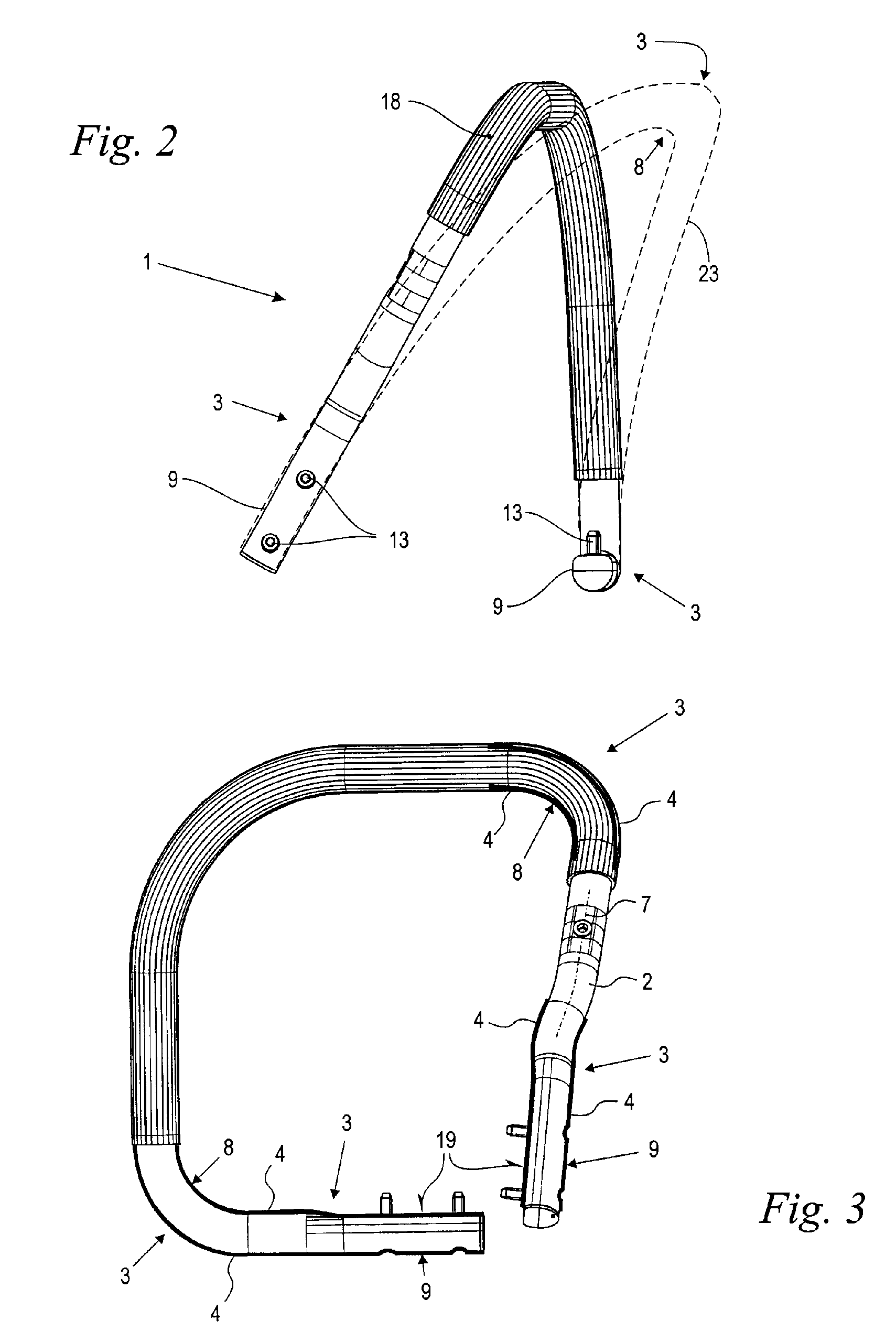
[0021]FIG. 2 shows in a side view details of the handle pipe 1 according to FIG. 1. The handle pipe 1 is covered by a grip hose 18 in t...


PUM


Abstract

A handle of a hand-held working tool has a handle pipe made of a laminate with fiber-reinforced plastic material. The handle pipe is reinforced by a locally adjusted laminate structure at locations of high dynamic vibration-caused deformation energy, respectively. The laminate of the handle pipe has a base laminate and an additional laminate provided at the locations of high dynamic vibration-caused deformation energy. The additional laminate is applied to the exterior of the base laminate.

Description

BACKGROUND OF THE INVENTION [0001] The invention relates to a handle of a handheld working tool (power tool) such as a motor chainsaw or the like, wherein the handle comprises a handle pipe that is manufactured of a laminate comprising a fiber-reinforced plastic material. The invention further relates to a working tool (power tool) having such a handle. [0002] When operating a handheld working tool (power tool), such as a motor chainsaw, a trimmer or the like, mechanical vibrations occur that can be caused by the running of a drive motor or by the driven cutting tool. The working tool (power tool) is held by a handle and guided during operation of the tool by means of the handle. The mass of the working tool forms together with the elastically deformable handle a vibratory system that can be excited by the exciting vibrations of the motor or the cutting tool. These vibrations can be felt by the operator's hand that grips the handle and guides the tool. Excessive vibrations can cause...

Claims


Application Information

Patent Timeline
IPC IPC(8): B25G1/10
CPCY10T16/476B27B17/0033
Inventor KEMMLER, RALF-RAINERGUIP, ANDREAS
Owner ANDREAS STIHL AG & CO KG
Why Eureka
Try Eureka