Method for auto-ignition combustion control

Active Publication Date: 2006-01-12
GM GLOBAL TECH OPERATIONS LLC
View PDF13 Cites 12 Cited by
  • Summary
  • Abstract
  • Description
  • Claims
  • Application Information

AI Technical Summary

Benefits of technology

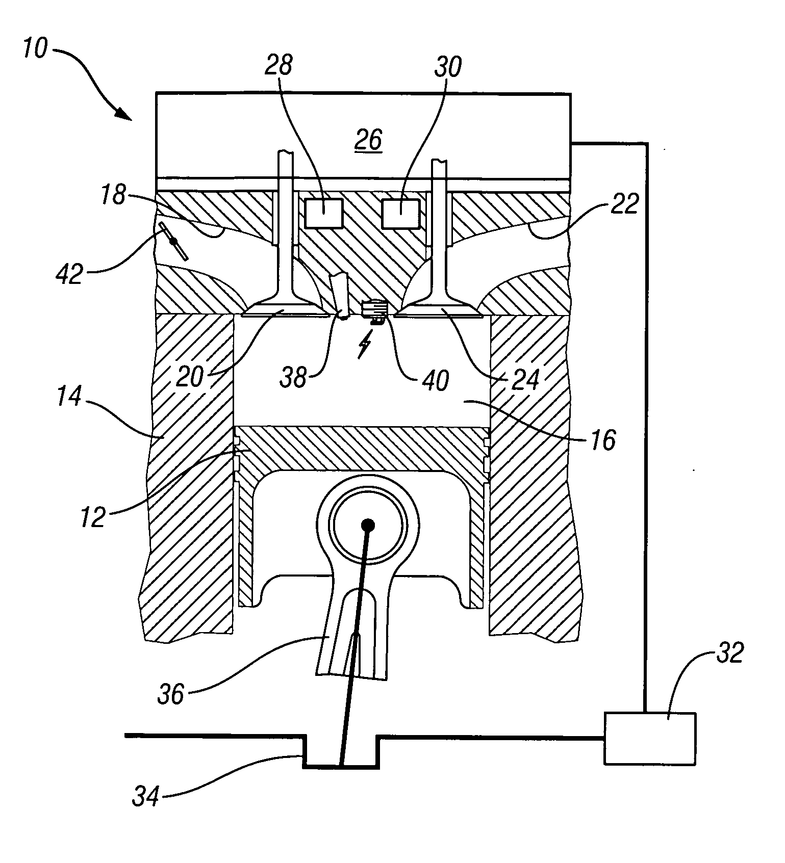
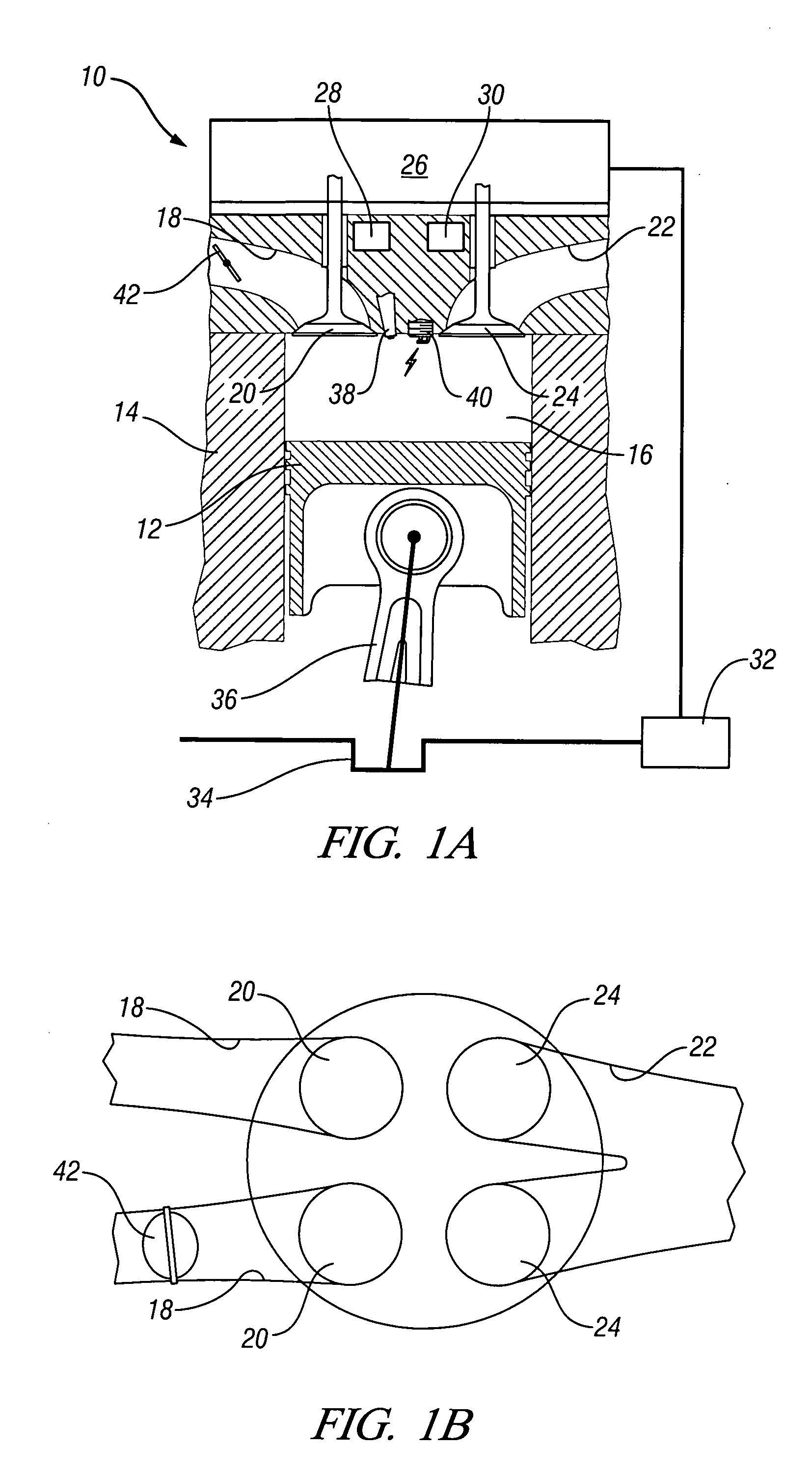
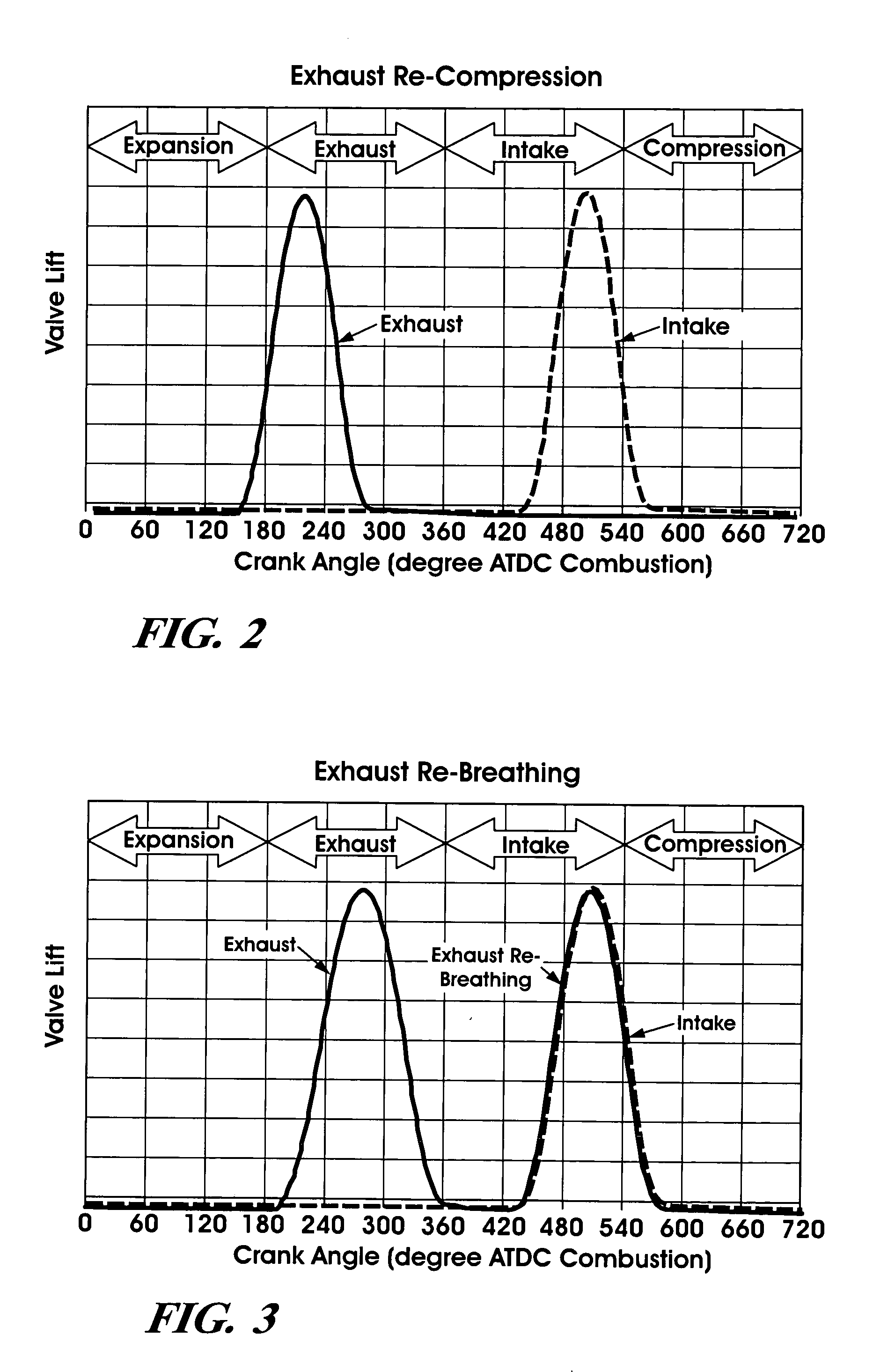
[0023] The present invention provides a method for controlling the air-fuel ratio in a gasoline direct-injection controlled auto-ignition engine at constant intake manifold pressure and fueling rate. In one embodiment, a flow control valve is employed in one branch of the intake runners for a two-intake-valve per cylinder engine. A swirl control valve that is currently used in a stratified-charge gasoline direct-injection engine for in-cylinder air motion control may be used as the flow control valve. The engine is operated with either an exhaust re-compression valve strategy or an exhaust re-breathing valve strategy. Variation of the flow

Problems solved by technology

In particular, closing the flow control valve results in lower delivered air-fuel ratio at a fixed intake manifold pressure for all valve strategies and the rate o

Method used


Image

  • Method for auto-ignition combustion control
  • Method for auto-ignition combustion control
  • Method for auto-ignition combustion control

Examples


Example

[0043] Although valve lift was used in the second embodiment of the method for air-fuel ratio control, it is equally effective if valve duration is used instead. Further, while the intake valve 20 and exhaust valve 24 in the above embodiments are electro-hydraulically actuated, they may be actuated mechanically or electrically using electromagnetic force.

[0044] While the invention has been described by reference to certain preferred embodiments, it should be understood that numerous changes could be made within the spirit and scope of the inventive concepts described. Accordingly, it is intended that the invention not be limited to the disclosed embodiments, but that it have the full scope permitted by the language of the following claims.


PUM


Abstract

A method is disclosed for controlling the air-fuel ratio in a four-stroke gasoline direct-injection controlled auto-ignition combustion. The engine is operated with two sequential pairs of expansion and contraction strokes during two revolutions of the engine crank, the two revolutions defining a combustion cycle. A system is employed for variably actuating the intake and exhaust valves and adjusting the flow of air and burned gases entering the combustion chamber. Adjusting the flow affects the resulting air-fuel ratio in the combustion chamber. The valve actuating system is employable to operate the intake and exhaust valves with an exhaust re-compression or an exhaust re-breathing valve strategy. Either valve strategy affects the air-fuel ratio in the cylinder and causes a proportion of burned gases from previous combustion cycles to be retained in the cylinder to provide the necessary conditions for auto-ignition of the air-fuel mixture.

Description

CROSS-REFERENCE TO RELATED APPLICATIONS [0001] This application claims priority from U.S. Provisional Patent Application No. 60 / 587,163 filed Jul. 12, 2004.TECHNICAL FIELD [0002] This invention relates to a method for controlling the auto-ignition combustion process in a gasoline direct-injection controlled auto-ignition engine at light load and during transient operation. BACKGROUND OF THE INVENTION [0003] To improve thermal efficiency of gasoline internal combustion engines, dilute combustion, using either air or re-circulated exhaust gas, is known to give enhanced thermal efficiency and low NOx emissions. There is, however, a limit at which an engine can be operated with a diluted mixture because of misfire and combustion instability as a result of a slow burn. Known methods to extend the dilution limit include: 1) improving ignitability of the mixture by enhancing ignition and fuel preparation; 2) increasing the flame speed by introducing charge motion and turbulence; and 3) ope...

Claims


Application Information

Patent Timeline
IPC IPC(8): F02B3/00F02M25/07F01L1/34
CPCF01L13/0015Y02T10/18F02B17/005F02B23/101F02B2023/108F02B2075/125F02D13/0207F02D13/0246F02D13/0253F02D13/0265F02D13/0273F02D41/0002F02D41/006F02D41/008F02D41/3035F02D2041/001F02D2041/002F02M25/0752Y02T10/128Y02T10/123Y02T10/47F02B1/12F02M26/01Y02T10/12Y02T10/40
Inventor KUO, TANG-WEIENG, JAMES A.BROWN, BARRY L.
Owner GM GLOBAL TECH OPERATIONS LLC
Why Eureka
Try Eureka