[0021] It is an object of the present invention to provide a fluid-filled vibration damping bushing that ensures the required vibration isolating or damping ability and stopper ability, while reducing the number of vulcanized parts required overall and the
resultant manufacturing cost.
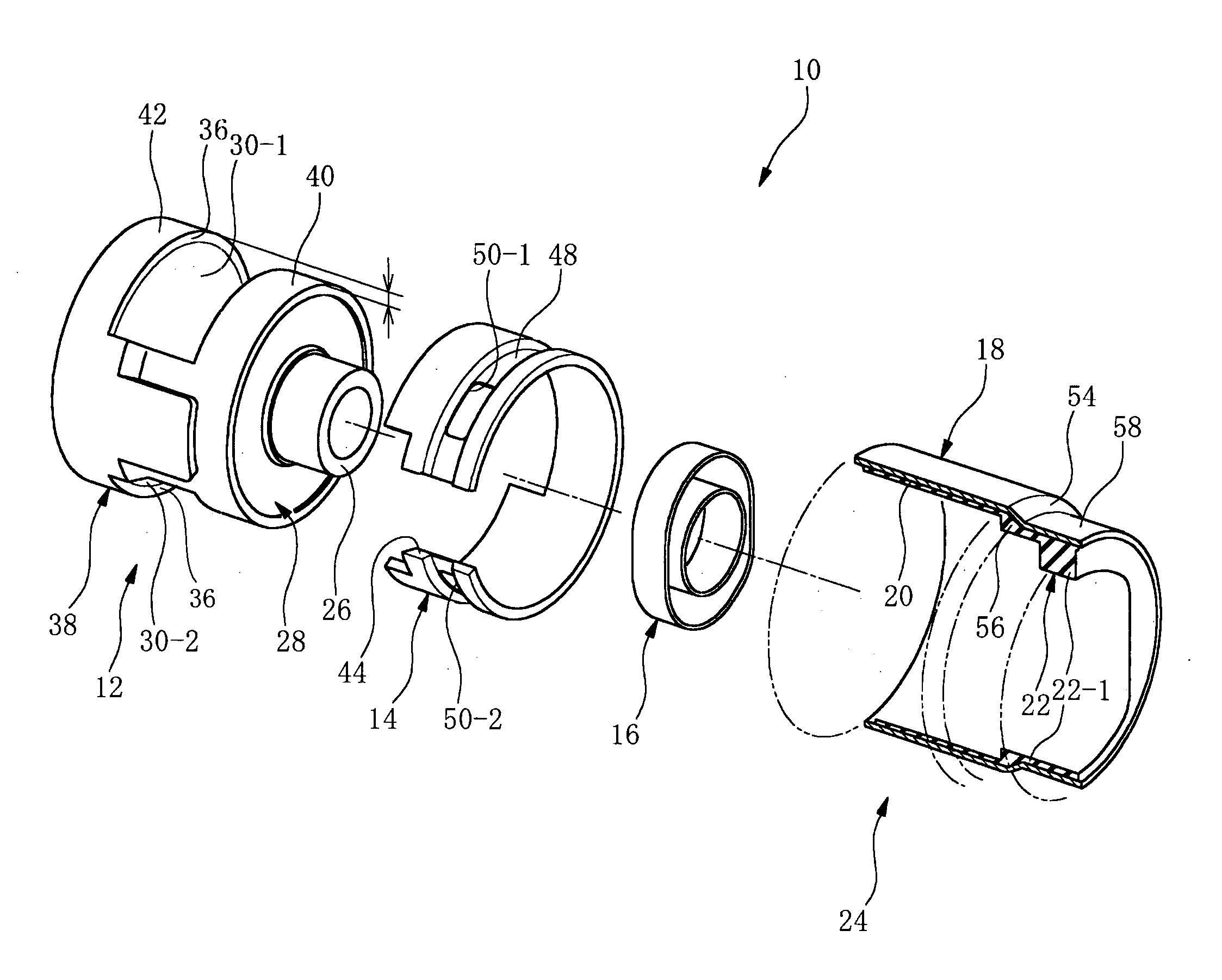
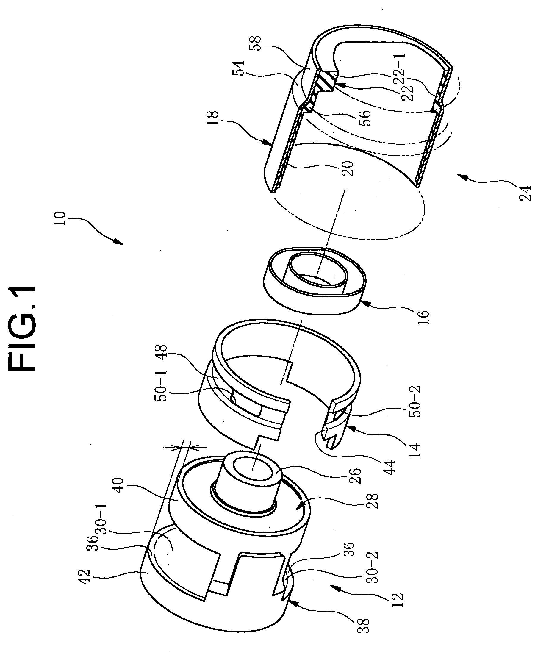
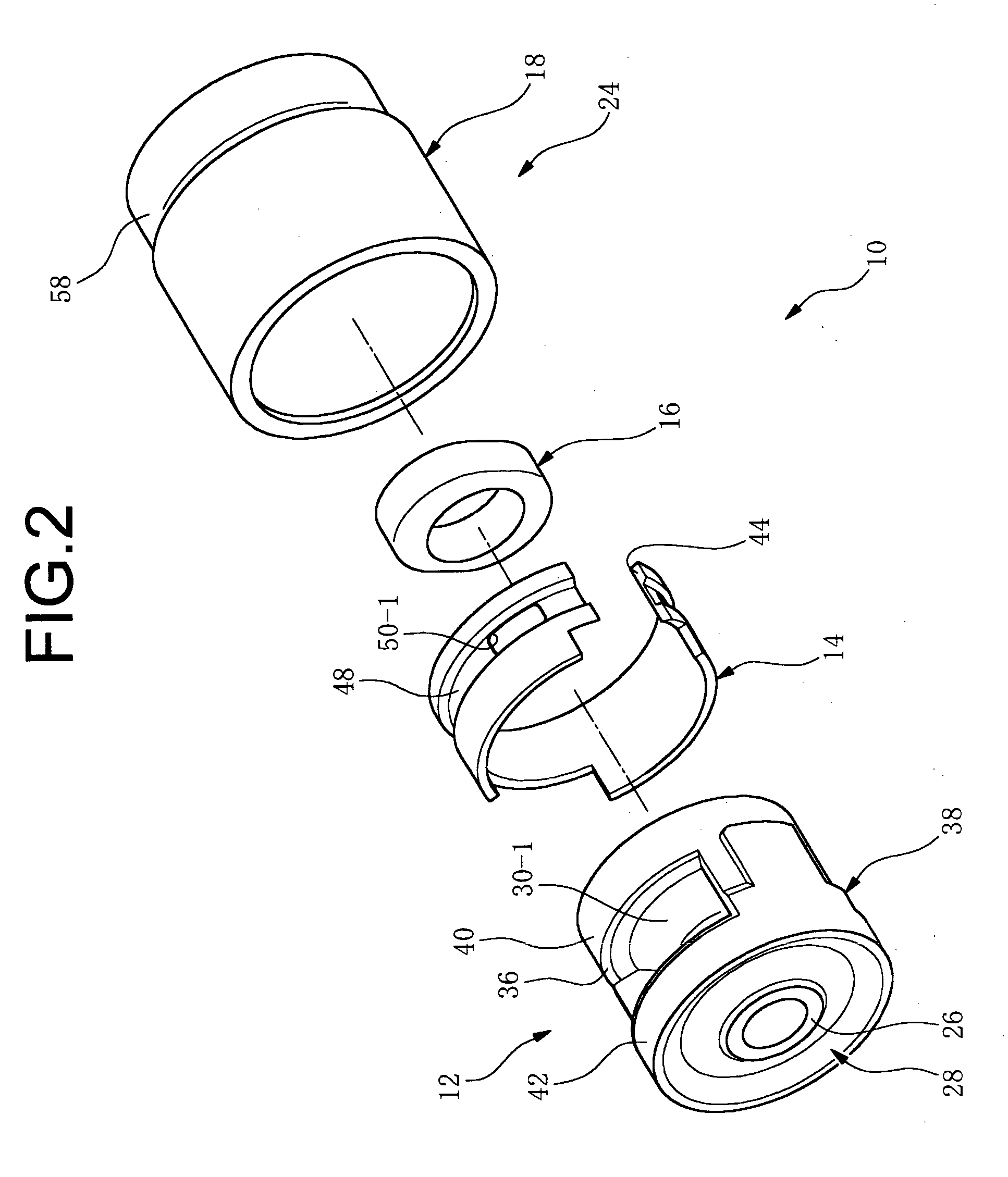
[0023] A first mode of the invention provides a fluid-filled vibration damping bushing comprising: (I) a bushing body having an inner tubular metal member, an outer
peripheral sleeve disposed coaxially about the inner tubular metal and a base rubber interposed between and elastically connected the inner tubular metal member and the outer peripheral sleeve, the base rubber having a pair of depressions recessed towards an inner tubular metal member side and open in an outer circumferential surface of the base rubber, so as to provide mutually independent first and second fluid chambers having a non-compressible fluid sealed therein, and the outer peripheral sleeve having a pair of aperture window of shape corresponding to openings of the first and second fluid chamber; (II) an orifice member at least partially defining an orifice passage extending between the openings of the first and second fluid chamber so that the fluid sealed within the first and second fluid chambers is caused to flow between the chambers; (III) an outer tubular metal member having a seal rubber layer integrally bonded by
vulcanization to an inner circumferential surface thereof for liquid-tight sealing of the first and second fluid chambers, and fastened to an outer circumferential surface of the outer peripheral sleeve via the seal rubber layer, closing off the opening of the first and second fluid chambers; and (IV) a stopper rubber constituted as a separate element from the base rubber, disposed at a circumferential location corresponding at a minimum to either the first or second fluid chamber, for restricting
relative displacement of the inner tubular metal member and outer tubular metal member in the axis-
perpendicular direction, wherein the stopper rubber is formed separately from the orifice member and is bonded to a first axial end portion of the outer tubular metal member at a location outside the first and second fluid chambers so as to face toward the inner tubular member, and the outer tubular metal member with the stopper rubber attached thereto is inserted onto the bush body from an other axial end thereof.
[0028] According to the present invention, as described hereinabove, the stopper rubber formed separately from the orifice member, is integrally bonded (by
vulcanization, for example) facing the inner tubular metal member in an exposed state at the axial end of the outer tubular metal member situated to the outside of the fluid chambers and outwardly in axial direction of the base rubber. Therefore, two components, namely, a rubber unitary vulcanized part consisting of the bushing body, and an unitary vulcanized part composed of the outer tubular metal member, the seal rubber layer, and the stopper rubber, suffice, whereby the number of vulcanized parts may be reduced as compared to the prior art, so that the costs associated with the fluid-filled vibration damping bushing can be lowered.
[0031] Where the stopper member is integrally bonded by vulcanization to the orifice member as in the past, overall thickness increases, whereby it becomes impossible in
actual practice to attach the orifice member by inserting it, together with the rubber stopper, into the base rubber in the axial direction. With the present invention on the other hand, since the stopper rubber is provided outside the fluid chamber in a form separated from the orifice member, it becomes possible for the orifice member to be of unitary construction continuous in the circumferential direction, and to be attached to the base rubber in the axial direction. In this instance, the orifice member, which in the past was constructed of two separate parts, can now be constituted as a
single component, whereby it becomes possible to further lower the cost of the fluid-filled vibration damping bushing.
[0033] According to the fourth mode, on the other hand, the orifice member constitutes the unitary structure of C ring shape continuous in the circumferential direction, the gap between the circumferential ends of the bushing body adjacent to the first fluid chamber and the second fluid chamber is smaller than the gap between the circumferential ends of the orifice member, and the orifice member is attached by being inserted into the bushing body in the axis-
perpendicular direction. Even with this arrangement, the orifice member can be constituted as an unitary structure and attached easily to the bushing body.
[0034] In the present invention, the bushing body in the out tubular metal member, more specifically a portion situated at an axial end of the outer peripheral sleeve, constitutes a shoulder portion facing the inner tubular metal member side, and this is made to contact an axial end of the outer peripheral sleeve, with the stopper rubber integrally vulcanization bonded to the inner circumferential surface of the small-
diameter portion continuing on from the shoulder portion (Fifth Mode). By means of this arrangement, the gap between the inner tubular metal member and the stopper rubber can readily be given the appropriate spacing needed for stopper action. Additionally, when the outer tubular metal member is fitted externally onto the bushing body, the relative positional relationship of the bushing body and the outer tubular metal member can be readily positioned.

