
Apparatus and method to control torque and voltage of an AC machine

a technology of ac machines and actuators, applied in the direction of pulse technique, motor/generator/converter stoppers, dynamo-electric converter control, etc., can solve the problems of limited voltage, inability to provide and maintain the required starting torque, and non-optimal starter performance, so as to achieve the effect of increasing the total torqu

Active Publication Date: 2006-01-12
HONEYWELL INT INC
View PDF26 Cites 25 Cited by
  • Summary
  • Abstract
  • Description
  • Claims
  • Application Information

AI Technical Summary

Benefits of technology

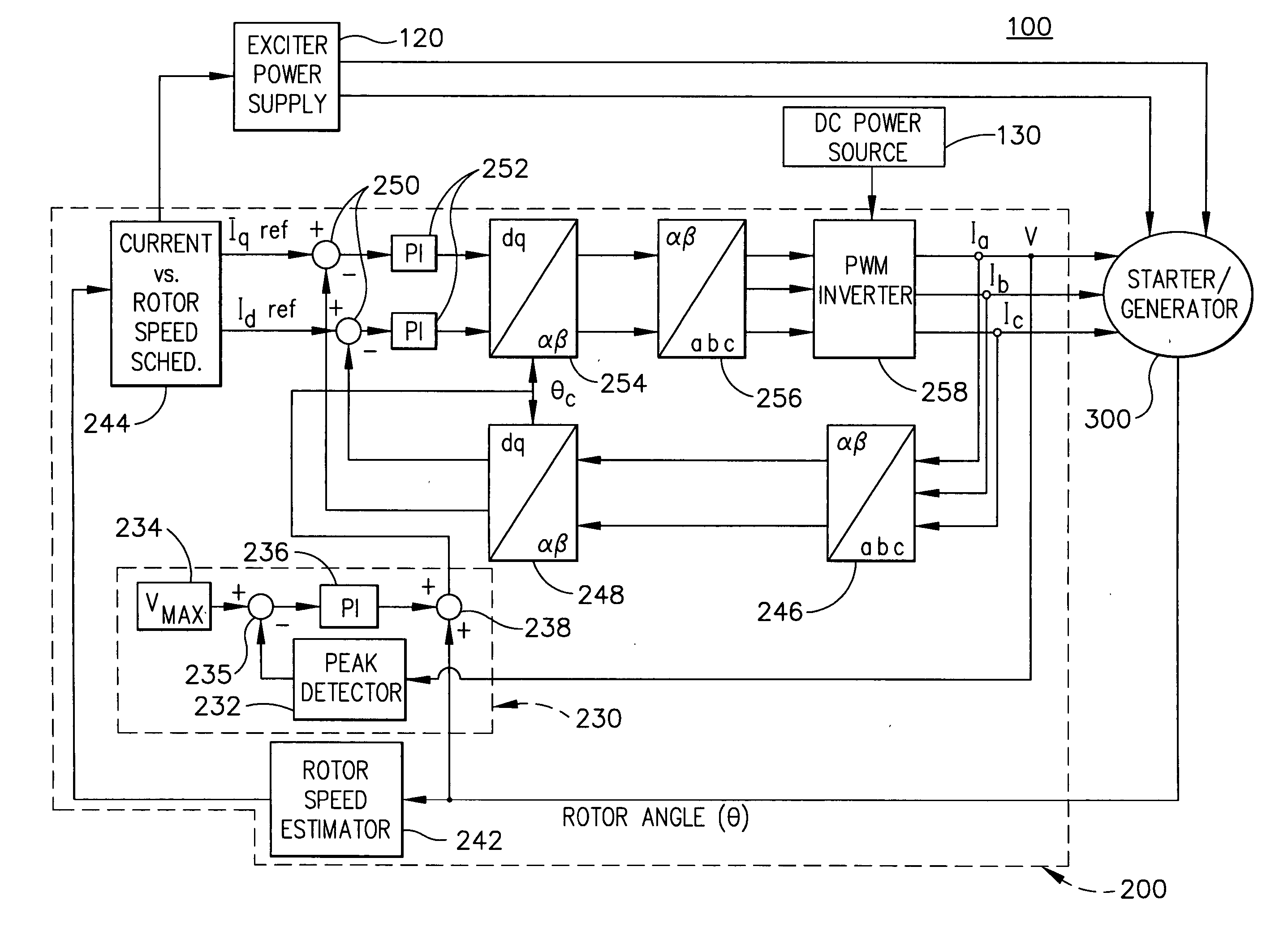
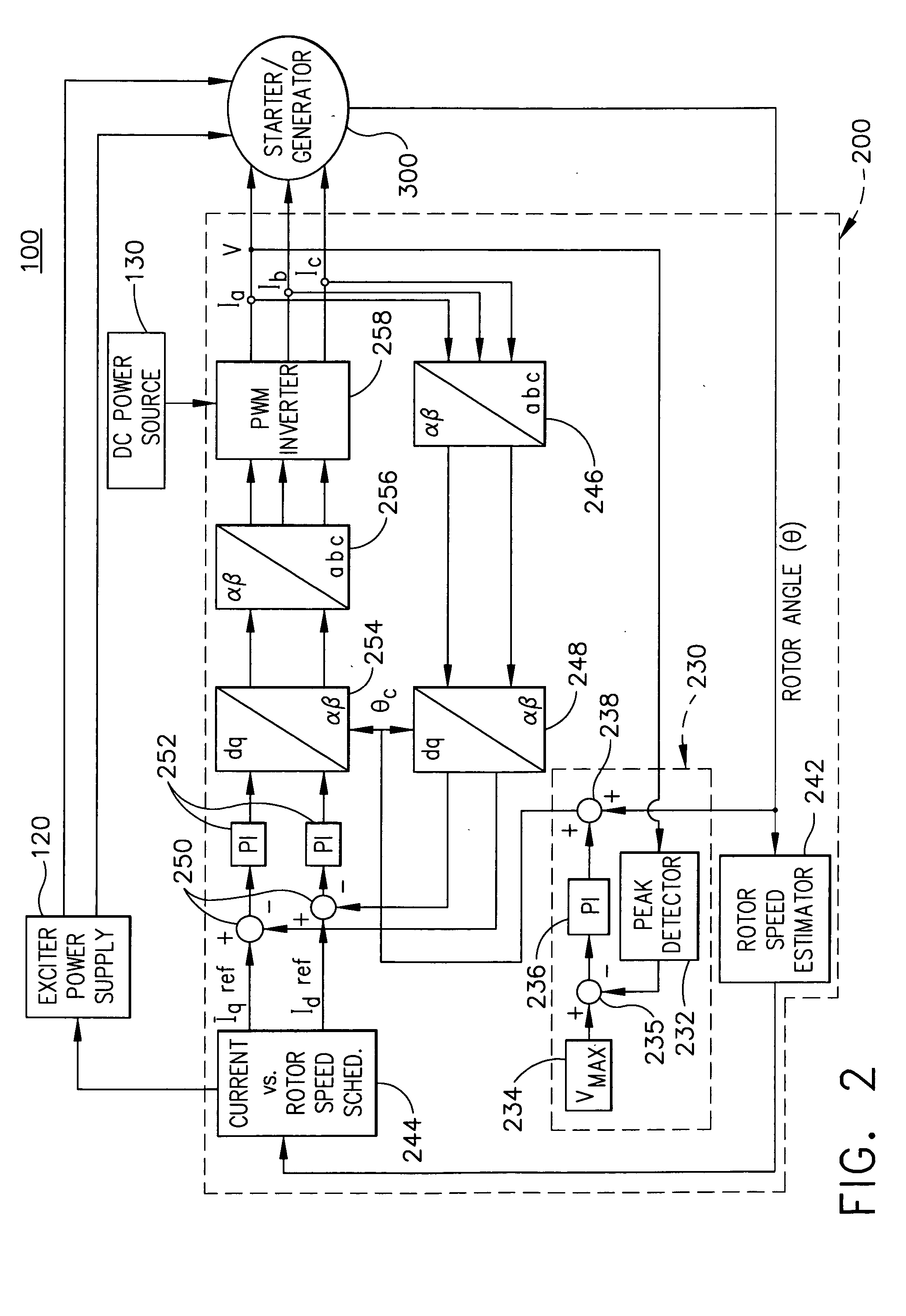
[0008] In another aspect, the present invention is a power converter controlling apparatus for controlling a power converter of a synchronous machine drive system, the controlling apparatus comprising: a current controller for generating power converter command signals by determining position and speed of a rotor of the synchronous machine; regulating a current vector relative to a reference frame, having a direct-axis component and a quadrature-axis component, the regulating

Problems solved by technology

It is often difficult to provide and maintain the required starting torque, particularly in the constant power region (corresponding the high speed range) of the starting operation, with a power conversion device having a limited input / output voltage.
This limitation in voltage is typically due to a fixed DC link available as input to the power conversion device.
This limitation in existing systems results in non-optimal starter performance due to insufficient torque or due to the requirement for increased voltage (i.e., exceeding a maximum level).
This DC link voltage is limited by practical considerations, such as the maximum voltage of the power supply, the component rating, etc.

Method used


Image

  • Apparatus and method to control torque and voltage of an AC machine
  • Apparatus and method to control torque and voltage of an AC machine
  • Apparatus and method to control torque and voltage of an AC machine

Examples


Embodiment Construction

[0015] Embodiments of the present invention are more specifically set forth in the following description, with reference to the appended drawings. In the following description and accompanying drawings, like elements are denoted with similar reference numbers. Further, well-known elements and related explanations are omitted so as not to obscure the inventive concepts presented herein.

[0016] In one aspect, the present invention is a method and apparatus for controlling torque and voltage of a synchronous AC machine. In one implementation, sufficient torque is generated in the high speed range of the machine while maintaining voltage at the input / output of a power conversion device that supplies AC voltage to the machine within acceptable limits. As will be described in greater detail below, this is achieved in one implementation of the present invention by changing the control angle of the power conversion device (e.g., inverter) in a closed loop to achieve: (1) positive reluctance...


PUM


Abstract

A method of controlling a power converter (258) of a synchronous machine drive system (100) determines position and speed of a rotor (350) of the synchronous machine (300); regulates a current vector relative to a reference frame, having a direct-axis component and a quadrature-axis component, the regulating step selectively causing the current vector to lag a quadrature axis of the machine (300); and outputs a command signal to the power converter (258) as a function of the regulating step. According to one implementation, this process creates higher total torque and maintains supply voltage within a maximum level during a high speed range of the machine.

Description

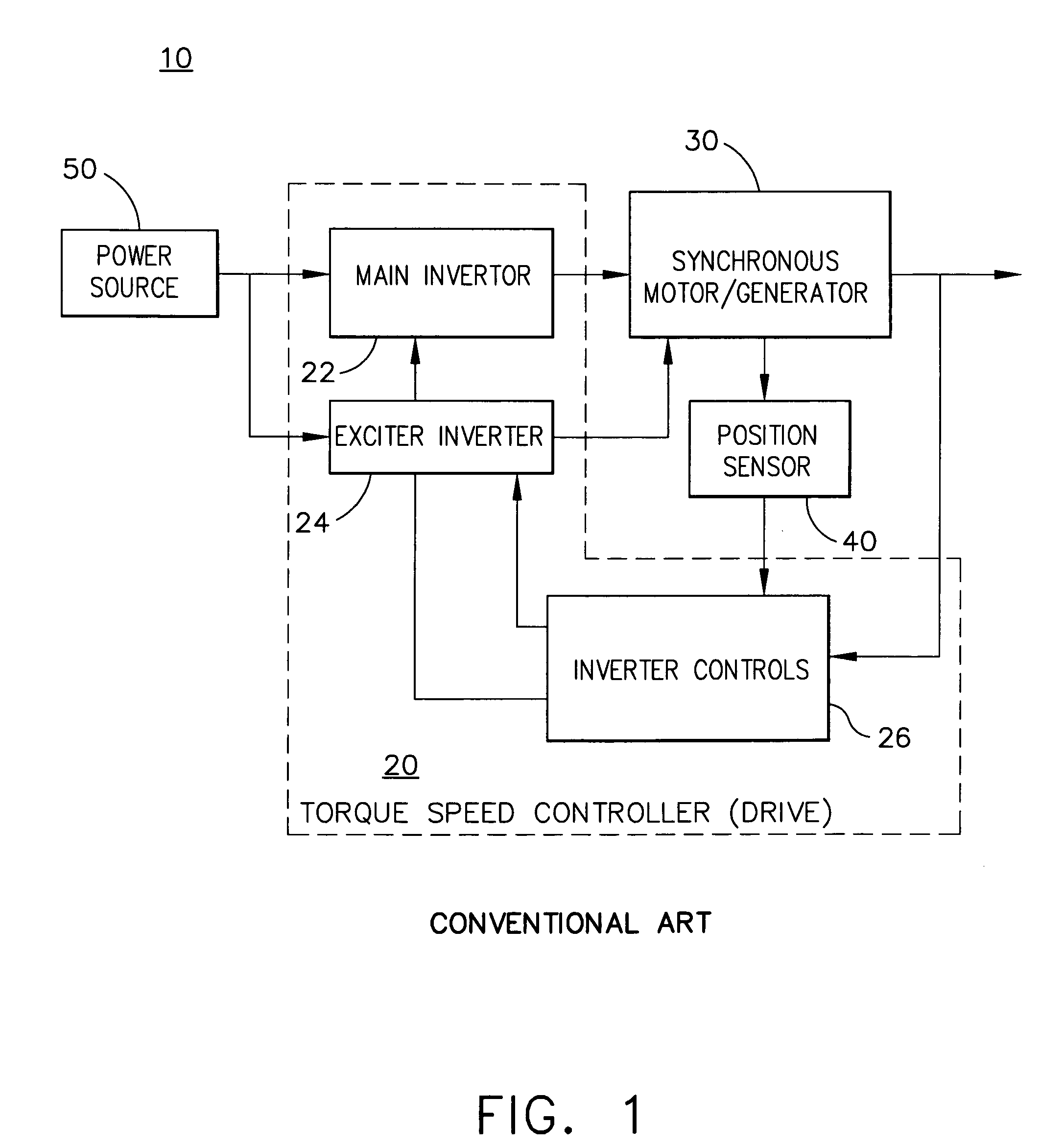
FIELD OF THE INVENTION [0001] The present invention relates to electrical power conversion, and more particularly to a controller and control technique for a power converter, such as an inverter of a synchronous AC motor drive system. BACKGROUND OF THE INVENTION [0002] A conventional electromechanical system, as utilized for example in the aerospace industry, includes a synchronous machine that generates multi-phase AC power from a rotating shaft, e.g., coupled to a gas turbine engine, and DC excitation. In addition to operating in a generator mode, the synchronous machine operates as a starter (motor) to start the aircraft engine. Following a successful engine start the system initiates the generator mode. In such applications where an AC electrical machine is used as a starter, it is desirable to provide a high starting torque with a power conversion device (e.g., inverter) having a limited input voltage. It is often difficult to provide and maintain the required starting torque, ...

Claims


Application Information

Patent Timeline
IPC IPC(8): H02P5/28H02P1/46
CPCH02P9/009H02P2101/30H02P21/0035H02P21/22
Inventor ANGHEL, CRISTIAN E.
Owner HONEYWELL INT INC
Learn More