
Method of diagnosing a broken bar fault in an induction motor

a technology of induction motor and fault diagnosis, which is applied in the direction of voltage-current phase angle, measurement devices, instruments, etc., can solve the problems of reducing productivity, affecting the operation of the induction motor, and reducing the probability of a sudden motor failur

Inactive Publication Date: 2006-01-12
MIRAFZAL BEHROOZ +1
View PDF13 Cites 22 Cited by
  • Summary
  • Abstract
  • Description
  • Claims
  • Application Information

AI Technical Summary

Benefits of technology

"The present invention provides a method and apparatus for diagnosing conductive discontinuities in the bars of rotors in induction motors, which is on-line and does not require motor disassembly or service interruption. The tool utilizes the motor monitoring and data processing capabilities already residing in the drive and does not require any additional sensor or device to the motor or motor-drive system. The method and apparatus are non-invasive of the motor operating environment and are based on a rotor's magnetic field pendulous oscillation phenomenon. The swing angle signal is measured and processed using a space vector formulation to obtain the fundamental component, which is used as an index for rotor fault diagnosis. The peak to peak of the swing angle signal indicates the degree of severity of a rotor cage fault. The invention provides a reliable and robust tool for diagnosing rotor faults in an efficient and effective manner."

Problems solved by technology

Industrial users of induction motors are interested in finding reliable procedures for rotor fault detection and diagnostics, since a sudden motor failure may be very damaging or catastrophic in an industrial system, in which the electric motor is a prime mover.
These motor failures can force expensive shutdowns of factory production and consequently reduce productivity.
Nevertheless, the probability of a sudden motor failure cannot be entirely ruled out.
Moreover, increasing the frequency of scheduled maintenance increases the cost and decreases the productivity of a system.
Moreover, this special arrangement increases the cost and decreases the reliability of the diagnostic system.
Determining slip frequency, from monitoring the current drawn by a motor in order to track the side band components as an index for fault diagnostic, reduces the reliability of the diagnostic system particularly for induction motor-drive systems, where the supply frequency varies by a closed loop control-drive system.

Method used


Image

  • Method of diagnosing a broken bar fault in an induction motor
  • Method of diagnosing a broken bar fault in an induction motor
  • Method of diagnosing a broken bar fault in an induction motor

Examples


Embodiment Construction

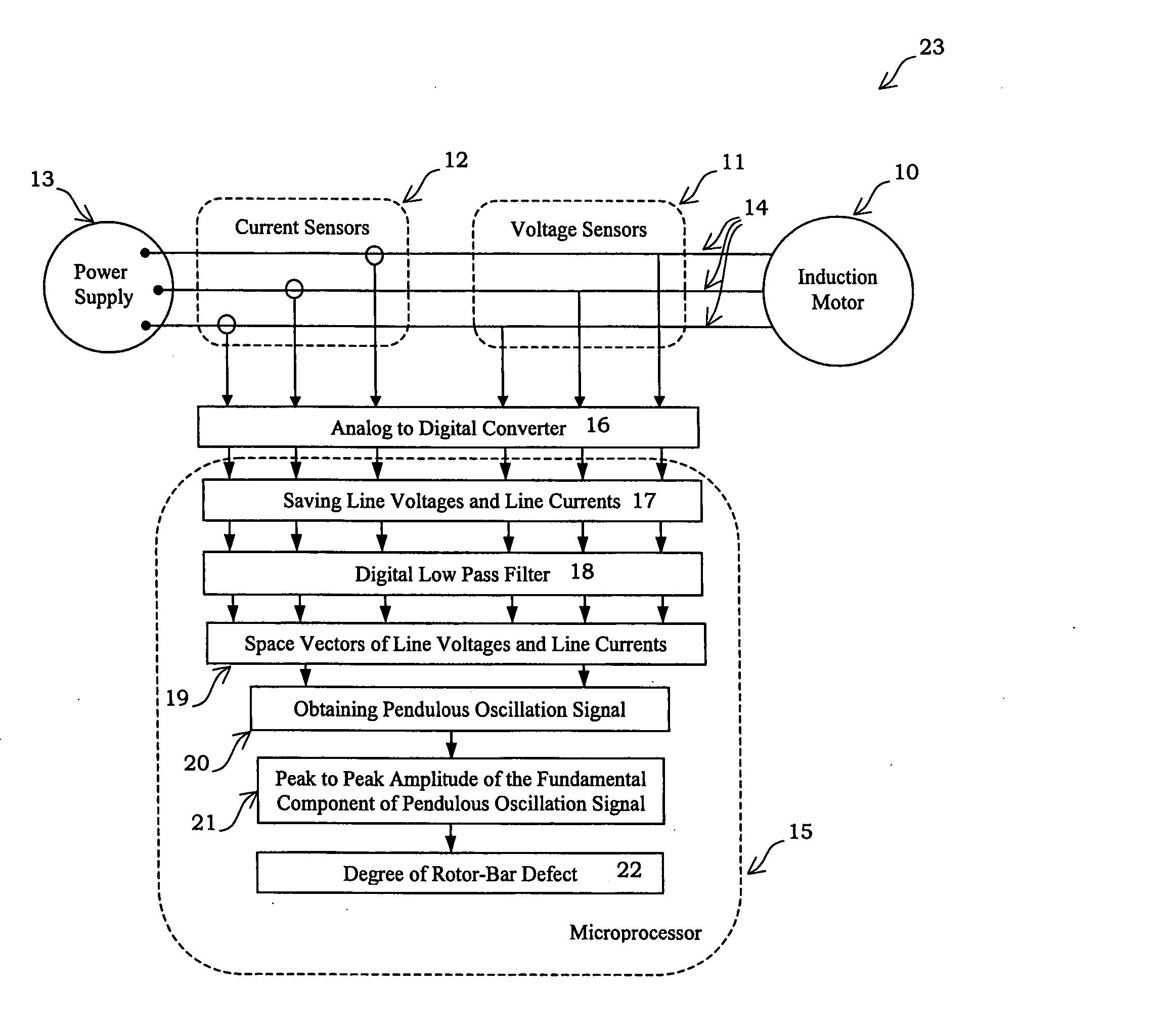
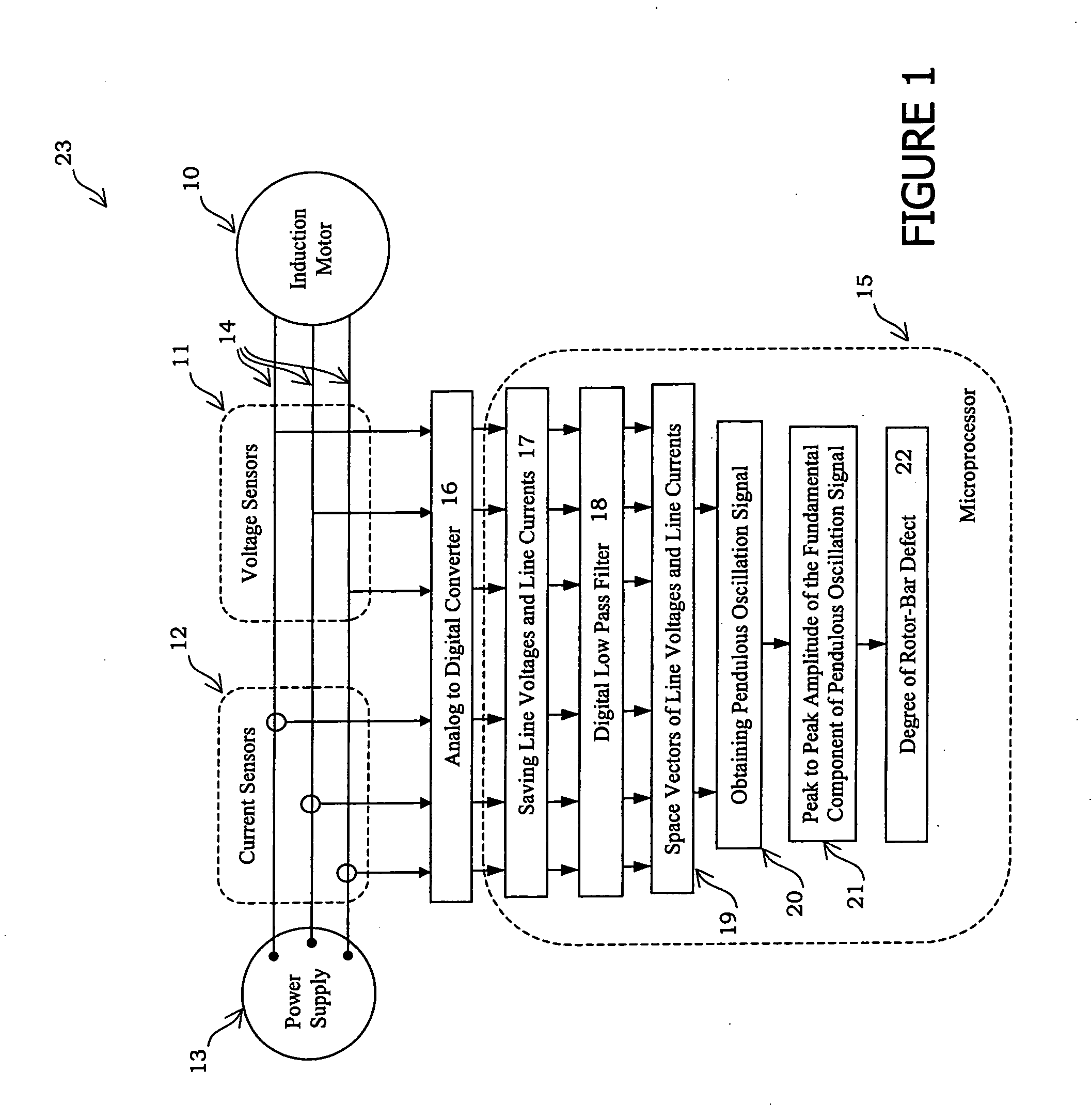
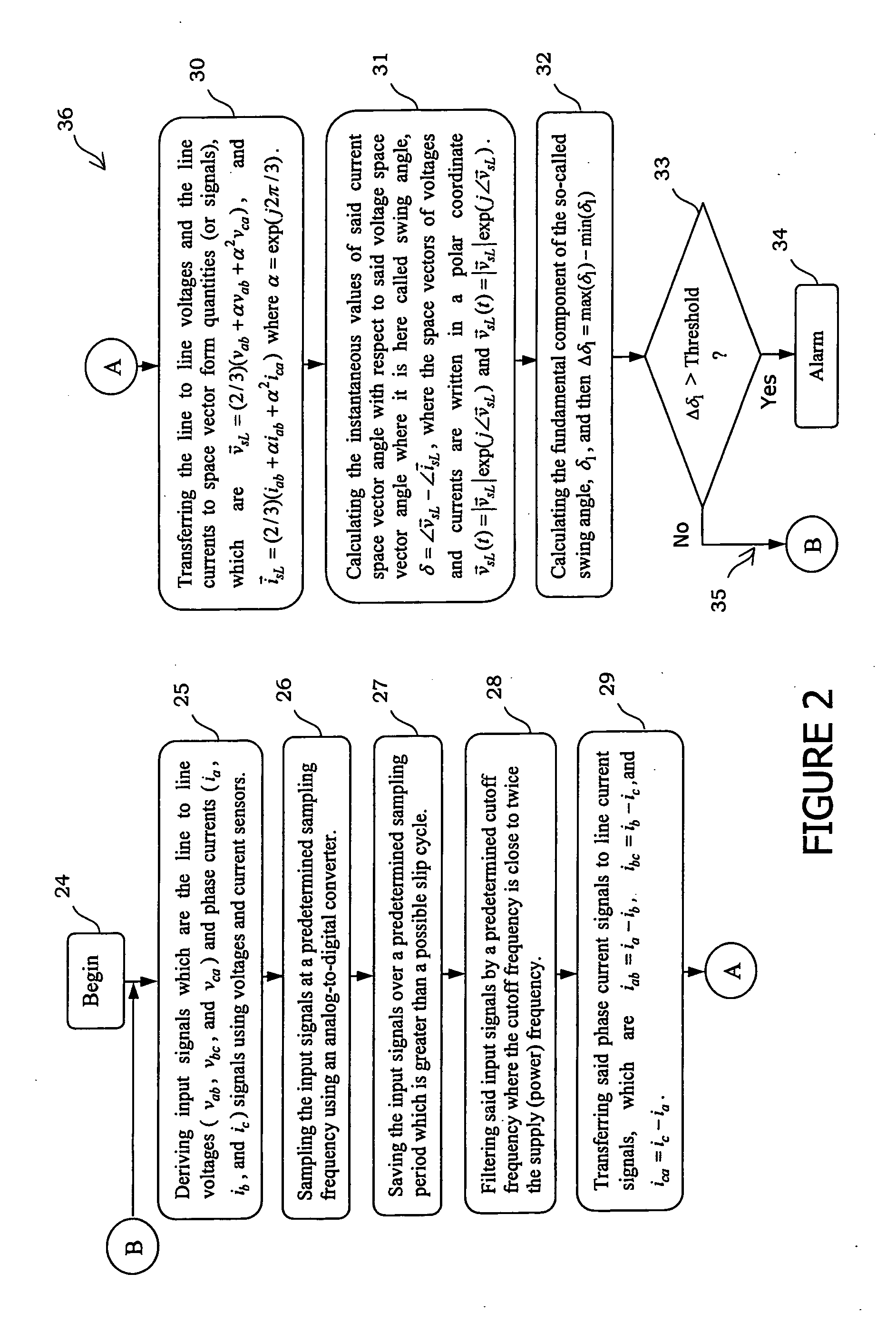
[0023] A well established principle is that magnetic fields rotate at synchronous speed in an induction motor. However, the rotor magnetic field and consequently the resultant magnetic field will have a pendulous oscillation superposed on its main motion at synchronous speed, when there is a rotor broken bar fault or a rotor bar defect. The frequency of this pendulous oscillation is equal to twice the slip frequency, which is typically less than 10% of the supply frequency. Moreover, the range (or peak to peak) of this oscillation (swing) increases with a corresponding increase in the number of broken bars or rotor bar defects. The magnitude of this pendulous oscillation and its- frequency are introduced and used in the present invention for induction motor rotor fault diagnostics.

[0024] The rotor magnetic field pendulous oscillation phenomenon is further described in Mirafzal and Demerdash, “Induction machine broken-bar fault diagnosis using the rotor magnetic field space-vector o...


PUM


Abstract

A method for diagnosing induction motor broken bar faults using the resultant magnetic field pendulous oscillation phenomenon is disclosed. Broken bar faults cause the resultant magnetic field of an induction motor to possess a pendulous oscillation modulating its inherent rotation at synchronous speed, and the range of this angular pendulous oscillation, referred to as the swing angle, increases with an increase in the number of broken bars. The angular pendulous oscillation is determined by calculating the space vectors derived from motor terminal voltages and currents. The variation in the angular difference between these two space vectors versus time is used to observe the resultant magnetic field's pendulous oscillation, and thus provide on-line rotor fault diagnostics.

Description

TECHNICAL FIELD [0001] The field of the invention is electrical machinery fault diagnostics and in particular it relates to the detection of rotor faults in induction motors. BACKGROUND OF THE INVENTION [0002] Industrial users of induction motors are interested in finding reliable procedures for rotor fault detection and diagnostics, since a sudden motor failure may be very damaging or catastrophic in an industrial system, in which the electric motor is a prime mover. These motor failures can force expensive shutdowns of factory production and consequently reduce productivity. Hence, maintenance schedules are provided to proactively reduce or prevent these failures. Nevertheless, the probability of a sudden motor failure cannot be entirely ruled out. Moreover, increasing the frequency of scheduled maintenance increases the cost and decreases the productivity of a system. Accordingly, an online fault diagnostic system becomes a valuable tool to increase industrial productivity and pr...

Claims


Application Information

Patent Timeline
Patent Type & Authority Applications(United States)
IPC IPC(8): G01R31/06
CPCG01R31/343
Inventor MIRAFZAL, BEHROOZDEMERDASH, NABEEL ALY OMAR
Owner MIRAFZAL BEHROOZ
Learn More