Integrated self-powered tire revolution counter

a self-powered, tire technology, applied in the direction of distance measurement, navigation instruments, instruments, etc., can solve the problem of obviating many complications involving tire electronics that are solely powered by batteries

Active Publication Date: 2006-01-12
MICHELIN RECH & TECH SA
View PDF7 Cites 44 Cited by
  • Summary
  • Abstract
  • Description
  • Claims
  • Application Information

AI Technical Summary

Benefits of technology

[0019] Some of this data may be determined from the generator signal or additional condition-responsive devices may be provided for sensing the desired parameters. Information in the microcontroller may then be relayed to a data reader either by direct contact method or via selective RF transmission. In one exemplary arrangement, data from the microcontroller or an outside source may be sent to an RFID device by way of direct contact, i.e., via direct electrical connection, and subsequently read out from the RFID device via RF transmission. One advantage of such a data contact-write, non-contact-read configuration is that data can be written as power is provided by the piezoelectric generator during tire rotation and data can be read out at tire stand still via RFID interrogator devices that may supply power to the RFID devices via a radiated RF field.

Problems solved by technology

Although batteries and battery-operated devices may still be incorporated with aspects of the present subject matter, many complications regarding tire electronics that are solely powered by batteries are obviated in accordance with the disclosed technology.

Method used


Image

  • Integrated self-powered tire revolution counter
  • Integrated self-powered tire revolution counter
  • Integrated self-powered tire revolution counter

Examples


Embodiment Construction

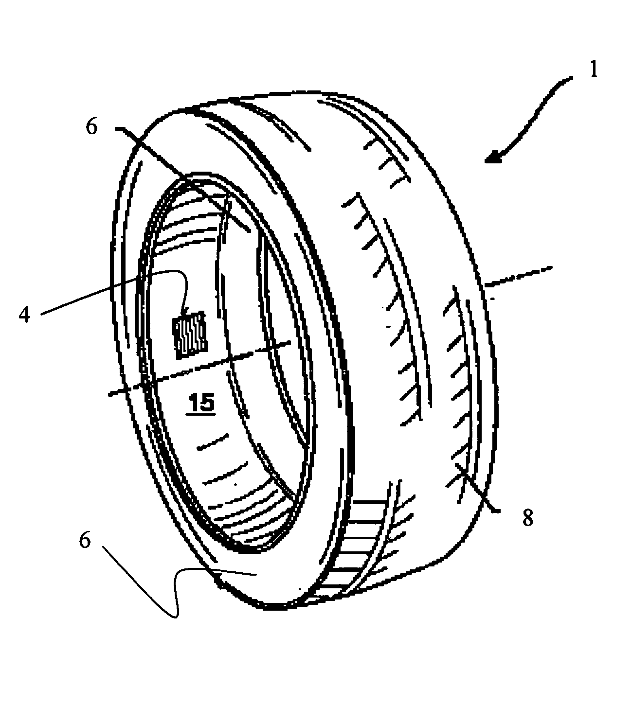
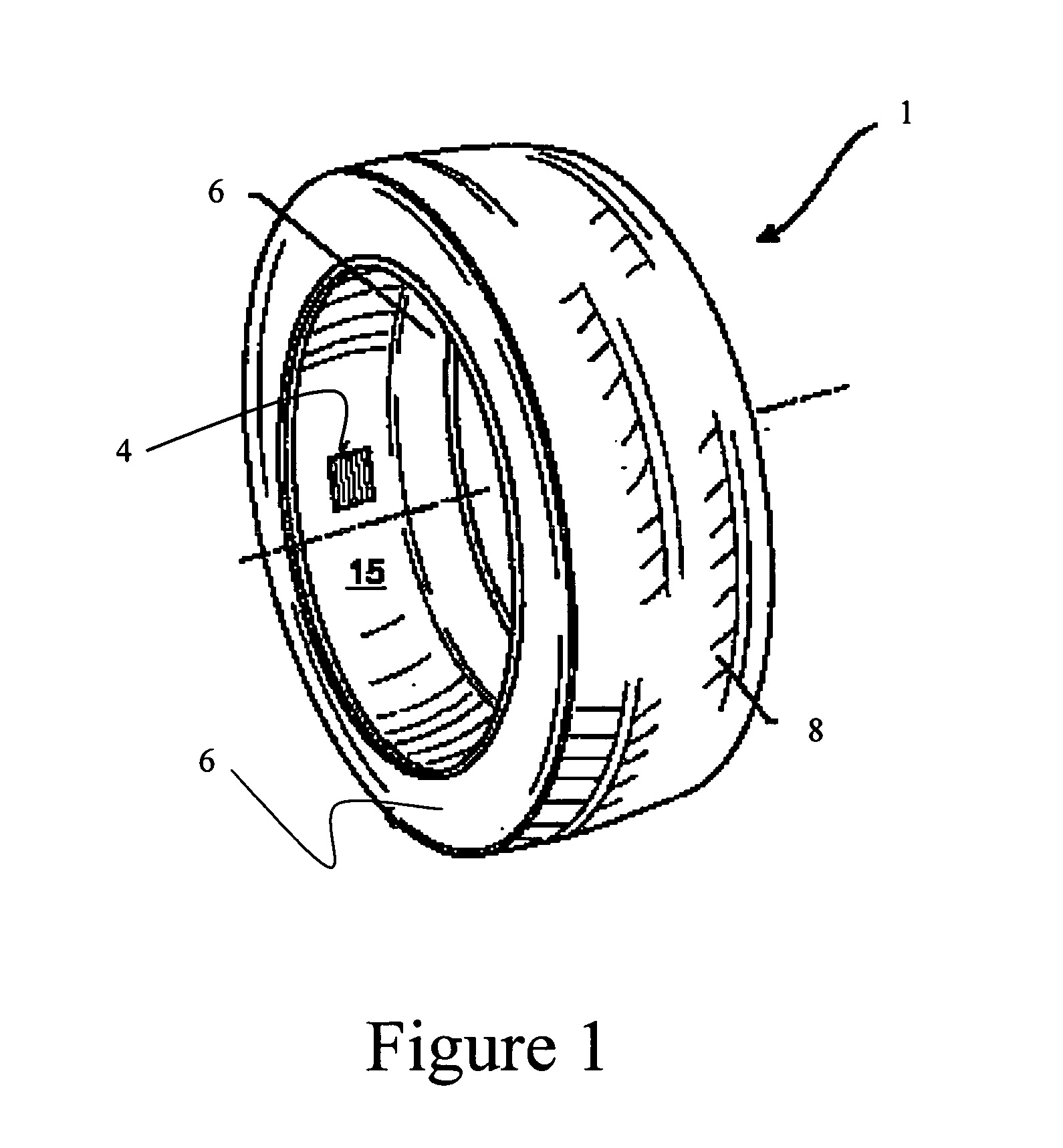
[0034] As discussed in the Summary of the Invention section, the present technology is particularly concerned with an improved system and method for counting tire revolutions and providing power to electronic systems integrated within a tire structure. In addition to generating power for the associated electronics, the mechanical strain associated with tire flexure produces a signal that is processed using a specialized algorithm to produce an accurate tire revolution count.

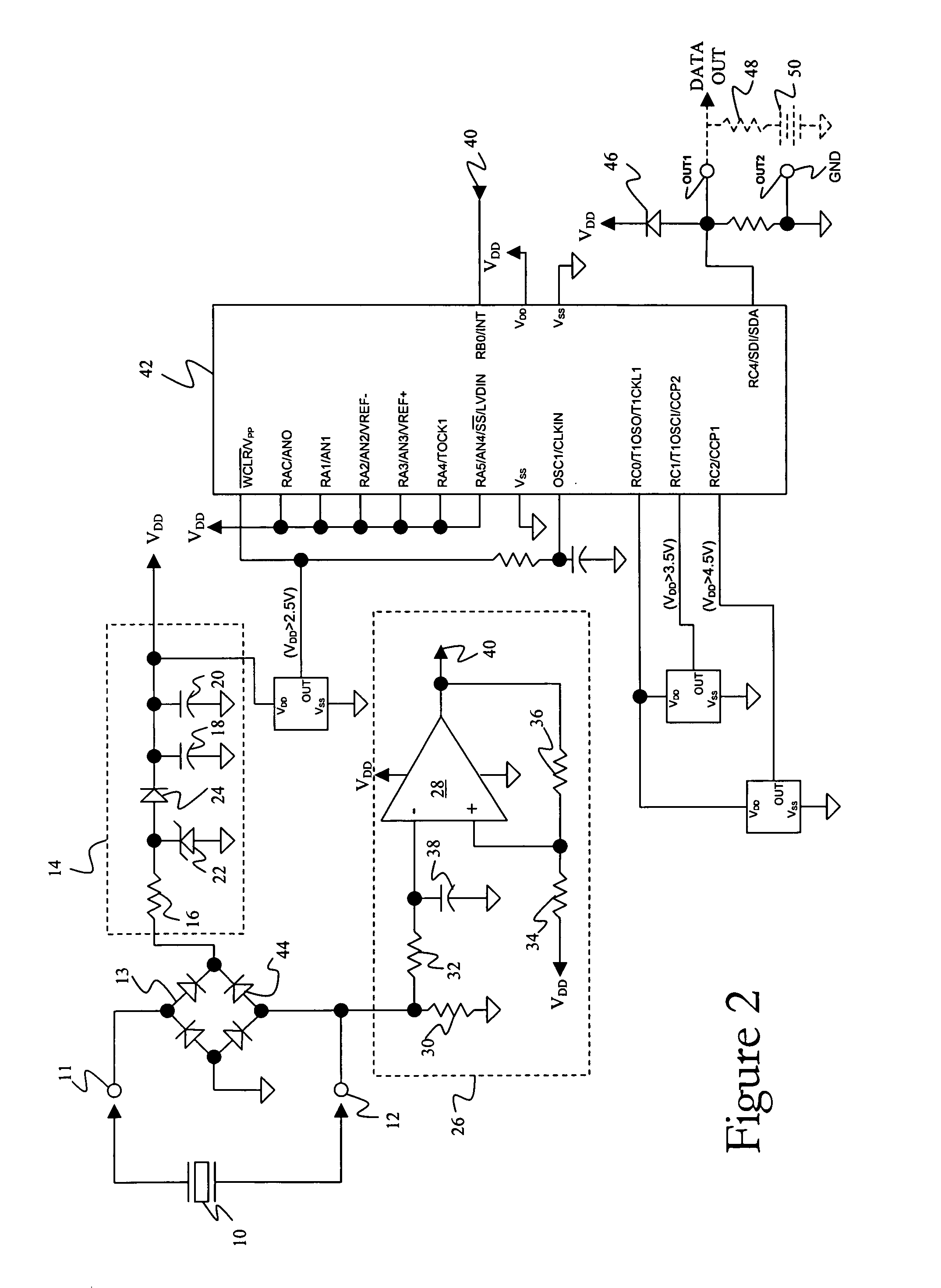
[0035] An integrated self-powered tire revolution counter in accordance with certain embodiments of the presently disclosed technology generally includes four principle components: a piezoelectric structure, a pulse detector, a power conditioner and a microcontroller. Aspects of each of these principle components, as well as other related components including the revolution counter's placement in and communication from within a tire or wheel assembly, will be discussed herein. Selected combinations of the aforem...


PUM


Abstract

A self-powered tire revolution counter includes a motion sensitive power generation mechanism, a power conditioner, a pulse detector, a microcontroller, and, optionally, a radio frequency (RF) transmitting device. In one exemplary embodiment, the power generation mechanism corresponds to a piezoelectric patch that, during movement, provides both operating electrical power and pulsed signals indicative of tire rotation. The power conditioner receives a generator signal from the power generation mechanism and produces a conditioned output voltage that can be used to power associated electronic devices, including the microcontroller. The pulse detector receives the generator signal and produces a detection signal whenever the generator signal meets a predetermined condition. The microcontroller is programmed to determine current and lifetime-accumulated values of selected pulse indications in the detection signal that meet predetermined criteria. Data corresponding to tire environment related parameters such as temperature, pressure, tire deflection, and/or vehicle speed may be stored in the microcontroller at times during tire rotation as power is supplied from the power generation mechanism through the power conditioner. Additional data may be supplied to the microcontroller directly from an external source and read from the microcontroller either by direct electrical contact or via selective RF transmission.

Description

FIELD OF THE INVENTION [0001] The present invention generally concerns a system and method for subjecting piezoelectric structures to the mechanical energy of conventional tire rotation, thereby generating electric power for integrated tire electronics and providing tire rotation signals. Piezoelectric technology is utilized to convert mechanical strain associated with tire flexure to a power supply output that can then power electronic components such as a microcontroller as well as radio frequency (RF) transmission devices. In addition to generating power for the associated electronics, the mechanical strain associated with the tire flexure produces a signal that is processed using a special algorithm to produce an accurate tire revolution count. BACKGROUND OF THE INVENTION [0002] The incorporation of electronic devices with pneumatic tire structures yields many practical advantages. Tire electronics may include sensors and other components for obtaining information regarding vari...

Claims


Application Information

Patent Timeline
Patent Type & Authority Applications(United States)
IPC IPC(8): B60C23/00
CPCB60C23/0411G01C22/00B60C23/0413
Inventor TYNDALL, PATRICK A.O'BRIEN, GEORGE PHILLIPSTEDROW, TIMOTHY R.
Owner MICHELIN RECH & TECH SA
Why Eureka
Try Eureka