

Electro-optical device, driving circuit of the same, driving method of the same, and electronic apparatus
a driving circuit and electronic equipment technology, applied in static indicating devices, instruments, electroluminescent light sources, etc., can solve problems such as difficult to cope with the deviation of the enable pulse, and inability to generate suitable sampling signals, so as to prevent the deterioration of display quality and improve the adjustment precision of phase. , the effect of simple structur
- Summary
- Abstract
- Description
- Claims
- Application Information
AI Technical Summary
Benefits of technology
Problems solved by technology
Method used
Image

Examples
Embodiment Construction
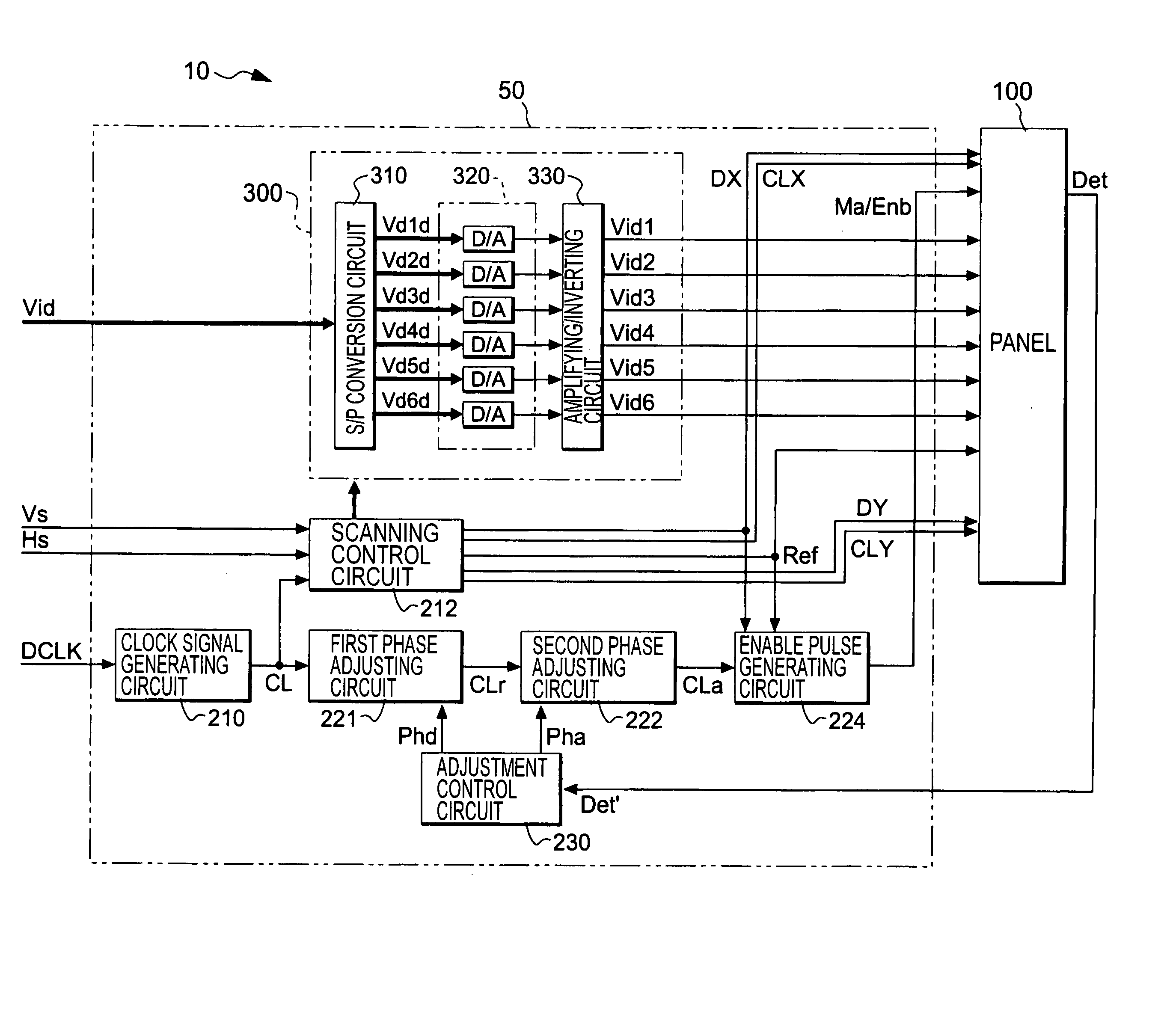
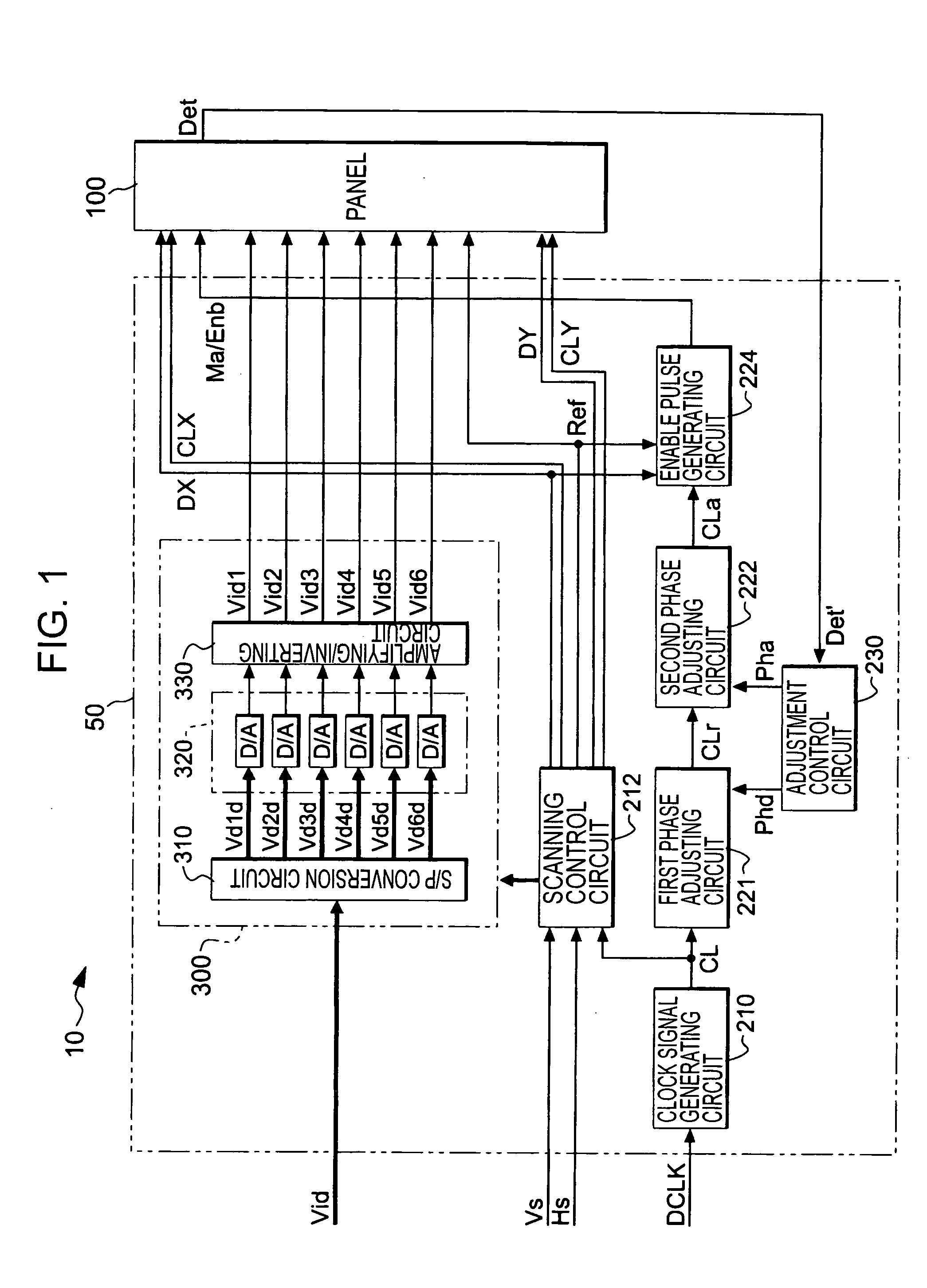
[0037] Hereinafter, embodiments of the present invention will be described with reference to the accompanying drawings. FIG. 1 is a block diagram showing the overall structure of an electro-optical device according to an embodiment of the present invention.
[0038] As shown in FIG. 1, an electro-optical device 10 is divided roughly into a processing circuit 50 and a panel 100. The processing circuit 50 is a circuit module formed on a printed substrate, and is connected to the panel 100 by an FPC (flexible printed circuit) substrate or the like, so that it supplies various signals and receives a monitoring signal, which will be described later.
[0039] The processing circuit 50 includes a clock signal generating circuit 210, a scanning control circuit 212, a first phase adjusting circuit 221, a second phase adjusting circuit 222, an enable pulse generating circuit 224, an adjustment control circuit 230, and a date signal supplying circuit 300.
[0040] The data signal supplying circuit 3...
PUM
 Abstract
Description
Claims
Application Information