
Thin film magnetic head, magnetic head device, magnetic recording/reproducing device and method for fabricating a thin film magnetic head

Inactive Publication Date: 2006-01-12
TDK CORPARATION
View PDF13 Cites 4 Cited by
  • Summary
  • Abstract
  • Description
  • Claims
  • Application Information

AI Technical Summary

Benefits of technology

[0015] It is another object of the present invention to provide a thin film magnetic head, a magnetic head device and a magnetic recording / reproducing drive device where electro-migration due to large current density can be prevented, and a method for fabricating the thin film magnetic head.
[0020] The reading element also includes a magnetic domain-controlling film to apply a perpendicular biasing magnetic field to the magnetoresistive effective film. With the perpendicular biasing magnetic field, a magnetic sensitive film constituting the magnetoresistive effective film is made single domain, and thus, Barkhausen noise due to the movement of magnetic wall can be prevented.
[0021] The pair of electrode films includes first electrode films, respectively, of which the forefronts are overlaid on the magnetoresistive effective film. In this case, since by setting appropriately the overlaying degree of the first electrode films, the first electrode films are formed beyond the non-sensitive regions of the magnetic domain-controlling films which are formed at the edge portions thereof, a given lead overlaying structure can be realized. Therefore, the performance of the thin film magnetic head can be enhanced, and the electro-migration due to large current density can be prevented.
[0023] In this case, the thicknesses of the forefronts of the first electrode films overlaying on the magnetoresistive effective film can be increased to prevent the blade shapes of the forefronts of the first electrode films. Therefore, a current density at the forefronts of the first electrode films can be reduced sufficiently, and thus, electro-migration due to large current density can be prevented.
[0024] Since the rising angle θ2 of the second electrode film is smaller than the rising angle θ1, the gap film can be formed thick at the forefront of the first electrode film through the wide opening of the second electrode film when the gap film is formed on the second electrode film and the magnetoresistive effective film by means of e.g., sputtering, so electric insulation failure between the top shielding film and the electrode films due to not sufficient thickness of the gap film can be prevented.
[0032] According to the fabricating method as mentioned above, the thin film magnetic head can be easily and precisely fabricated.

Problems solved by technology

As the electric resistance of the magnetic resistive sensor circuit is increased, the performance of the magnetic resistive sensor circuit is restricted and electro-migration due to large current density may occur.
When the rising angle of a second electrode film is set within 60-80 degrees as mentioned above, however, the gap film can not be formed sufficiently thick at the rising surface of the second electrode film, so that electric insulation can not be created between the second electrode film and the shielding film to be formed on the gap film.

Method used


Image

  • Thin film magnetic head, magnetic head device, magnetic recording/reproducing device and method for fabricating a thin film magnetic head
  • Thin film magnetic head, magnetic head device, magnetic recording/reproducing device and method for fabricating a thin film magnetic head
  • Thin film magnetic head, magnetic head device, magnetic recording/reproducing device and method for fabricating a thin film magnetic head

Examples


examples 1-6

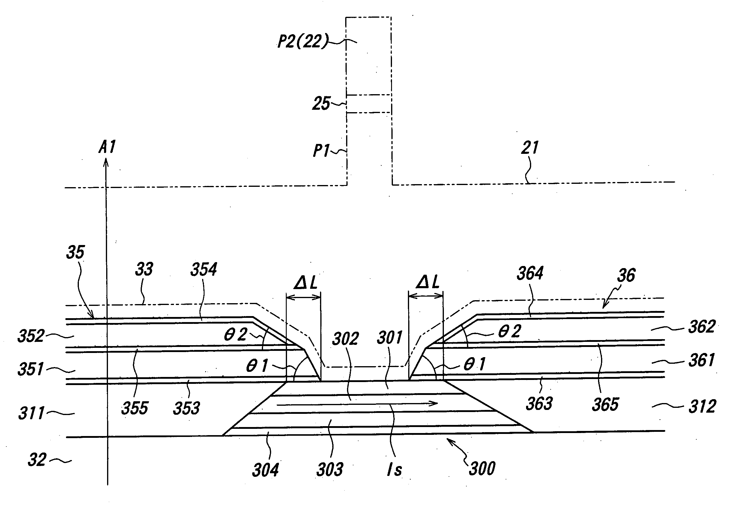
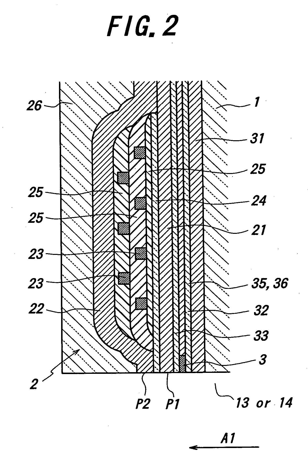
[0070] First of all, the first gap layer 32 was formed of Al2O3 in a thickness of 30 nm on the bottom shielding layer 31 made of NiFe (see, FIG. 2). Then, the magnetoresistive effective film 300 was formed of a SV film on the first gap film 32, and the magnetic domain-controlling films 311 and 312 were formed of CoPt at both edge portions of the film 300.

[0071] Then, the electrode films 35 and 36 were formed on the magneto-resistive effective film 300 and the magnetic domain-controlling films 311, 312 to form a lead overlaying structure, on which the second gap film 33 was formed of Al2O3. Then, the top shielding film (bottom magnetic film) 21 was formed on the second gap film 33.

[0072] In forming the lead overlaying structure with the electrode films 35 and 36, the inner angle θ1 of the first electrode films 351 and 361 was varied while the inner angle θ2 of the second electrode film 352 and 362 was maintained constant.


PUM

PropertyMeasurementUnit
Thicknessaaaaaaaaaa
Thicknessaaaaaaaaaa
Thicknessaaaaaaaaaa

Abstract

A magnetoresistive effective film responds commensurate with an external magnetic field. Magnetic domain-controlling films apply a perpendicular biasing magnetic field to the magnetoresistive effective film. The forefronts of first electrode films constituting a pair of electrode films are overlaid on the magnetoresistive effective film, and the forefront surfaces of the first electrode films are risen at an inner angle of θ1. Second electrode films are overlaid on the first electrode films, and the forefront surfaces of the second electrode films are risen at an inner angle of θ2 smaller than the inner angle θ1.

Description

BACKGROUND OF THE INVENTION [0001] 1. Field of the Invention [0002] This invention relates to a thin film magnetic head, a magnetic head device, a magnetic recording / reproducing device and a method for fabricating a thin film magnetic head. [0003] 2. Related Art Statement [0004] In a magnetic recording field, a thin film magnetic head having a spin-valve film (hereinafter, called as a “SV film”) as a reading element is mainly employed for developing the recording density and the miniaturization. [0005] The SV film is composed of a pinned layer, a non-magnetic layer and a free layer which are stacked in turn. The magnetization of the pinned layer is fixed in a given direction, and the magnetization of the free layer is rotated commensurate with an external magnetic field. The resistance of the SV film is minimized as the direction of the magnetization of the pinned layer is parallel to that of the free layer, and the resistance of the SV film is maximized as the direction of the magn...

Claims


Application Information

Patent Timeline
IPC IPC(8): G11B5/127G11B5/33G11B5/39
CPCG11B5/3903Y10T29/49046G11B5/3967G11B5/3932
Inventor TERUNUMA, KOICHISHIMAZAWA, KOJIKAMIJIMA, AKIFUMI
Owner TDK CORPARATION
Features
  • Generate Ideas
  • Intellectual Property
  • Life Sciences
  • Materials
  • Tech Scout
  • Unparalleled Data Quality
  • Higher Quality Content
  • 60% Fewer Hallucinations
Learn More