Apparatus and method for fading frequency estimation

a technology of fading frequency and approximation method, which is applied in the direction of transmission monitoring, receiver monitoring, baseband system details, etc., can solve the problems of large variation in the amplitude of received waves, difficult to extract the first and second deviations from the fading component, etc., to achieve efficient and accurate estimation of fading frequency

Inactive Publication Date: 2006-01-12
FUJITSU LTD
View PDF1 Cites 18 Cited by
  • Summary
  • Abstract
  • Description
  • Claims
  • Application Information

AI Technical Summary

Benefits of technology

[0037] An object of the present invention is to estimate a fading frequency efficiently and accu...

Problems solved by technology

In receiving stations of mobile communication systems etc., the fading phenomenon that the amplitudes of received waves vary to a large extent occurs because having arrived via multiple paths whose individual transmission characteristics significantly vary, the received waves interfere with each other.
Therefore, it is needed to deter...

Method used


Image

  • Apparatus and method for fading frequency estimation
  • Apparatus and method for fading frequency estimation
  • Apparatus and method for fading frequency estimation

Examples


first embodiment

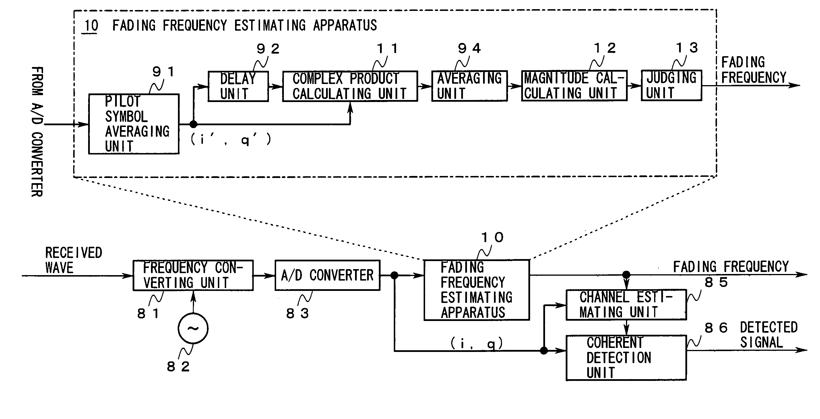
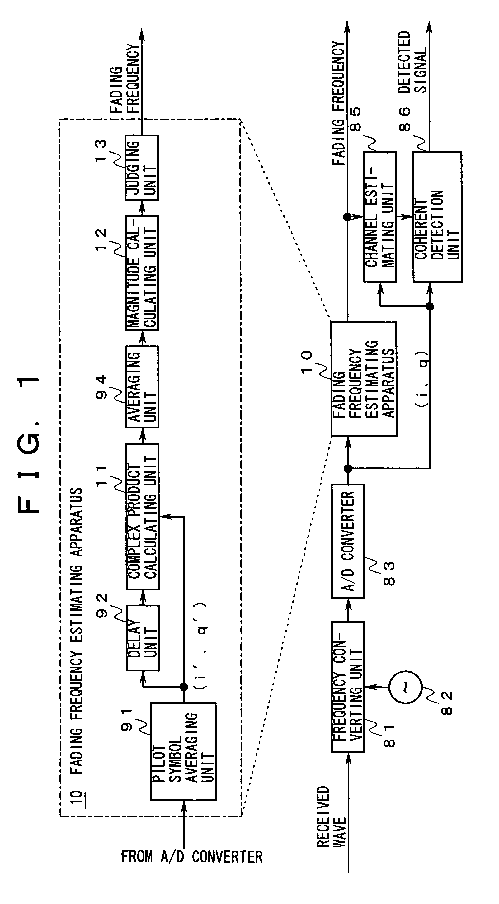
[0082]FIG. 1 shows a first embodiment of the invention.

[0083] As shown in FIG. 1, received waves are input to the input of a frequency converting unit 81 and the output of a local oscillator 82 is connected to a local frequency input of the frequency converting unit 81. The output of the frequency converting unit 81 is connected to the input of an A / D converter 83, and the output of the A / D converter 83 is connected to the input of a fading frequency estimating apparatus 10 and respective first inputs of a channel estimating unit 85 and a coherent detection unit 86. A fading frequency is obtained at the output of the fading frequency estimating apparatus 10, and the obtained fading frequency is supplied to a second input of the channel estimating unit 85. The output of the channel estimating unit 85 is connected to a second input of the coherent detection unit 86, and a detected signal is obtained at the output of the coherent detection unit 86.

[0084] The fading frequency estimati...

second embodiment

[0107]FIG. 5 shows a second embodiment of the invention.

[0108] In this embodiment, a fading frequency estimating apparatus 20 is provided in place of the fading frequency estimating apparatus 10 shown in FIG. 1. The fading frequency estimating apparatus 20 is composed of the following components: [0109] a pilot symbol averaging unit 91 that is disposed at the first stage; [0110] delay units 92-1 and 92-2 whose inputs are connected to the output of the pilot symbol averaging unit 91; [0111] a complex product calculating unit 11-1 whose first and second inputs are connected to the output of the delay unit 92-1 and the output of the pilot symbol averaging unit 91, respectively; [0112] a complex product calculating unit 11-2 whose first and second inputs are connected to the output of the delay unit 92-2 and the output of the pilot symbol averaging unit 91, respectively; [0113] a cascade-connected averaging unit94-1 and a magnitude calculating unit 12-1 that are connected to the output...

third embodiment

[0127]FIG. 6 shows a third embodiment of the invention.

[0128] As shown in FIG. 6, this embodiment is different from the second embodiment in that the following components are added to the second embodiment: [0129] a frequency deviation calculating unit 22-1 that is connected to the output of the averaging unit 94-1; [0130] a frequency deviation calculating unit 22-2 that is connected to the output of the averaging unit 94-2; and [0131] a frequency deviation averaging unit 23 whose first and second inputs are connected to the outputs of the frequency deviation calculating units 22-1 and 22-2, respectively, and produces a frequency deviation at the output.

[0132] In the following description, it is assumed that the frequency deviation calculating units 22-1 and 22-2 are included in the first system and the second system, respectively.

[0133] The operation of the third embodiment of the invention will be described below with reference to FIGS. 2 and 6.

[0134] The frequency deviation c...


PUM


Abstract

The invention relates to an apparatus and a method for estimating a fading frequency of incoming received waves in a receiving station of a radio communication system or radio transmission system. An object of the invention is to estimate a fading frequency efficiently and accurately without substantially complexing the configuration of the system. To this end, the invention provides an apparatus for estimating a fading frequency from a pilot signal in a reception signal, which includes a calculation unit for calculating a magnitude of a complex product of two symbols that are received at different instants, and an estimation unit for estimating a fading frequency according to the calculated magnitude of the complex product.

Description

CROSS REFERENCE TO RELATED APPLICATION [0001] This application is based upon and claims the benefit of priority from Japanese Patent Application No. 2004-180030, filed on Jun. 17, 2004, the entire contents of which are incorporated herein by reference.BACKGROUND OF THE INVENTION [0002] 1. Field of the Invention [0003] The present invention relates to an apparatus and a method for estimating a fading frequency of incoming received waves in a receiving station of a radio communication system or a radio transmission system. [0004] 2. Description of the Related Art [0005] In receiving stations of mobile communication systems etc., the fading phenomenon that the amplitudes of received waves vary to a large extent occurs because having arrived via multiple paths whose individual transmission characteristics significantly vary, the received waves interfere with each other. [0006] Such receiving stations reduce degradation in channel estimation accuracy by shortening the length of a pilot s...

Claims


Application Information

Patent Timeline
IPC IPC(8): H04B7/216G01R23/14G01R23/16H04B1/707H04B1/7097H04B7/26H04B17/00H04B17/29H04B17/309H04L25/02H04W24/00H04W24/08H04W88/02
CPCH04B2201/70701H04L25/0222H04L25/0202H04L25/0224
Inventor SHIMOMURA, TSUYOSHIKIMURA, DAIFUTAMI, TETSUHIROMINOWA, MORIHIKO
Owner FUJITSU LTD
Why Eureka
Try Eureka