
Acoustic diaphragm

a diaphragm and diaphragm technology, applied in the direction of diaphragms, electromechanical transducers, diaphragm construction, etc., can solve the problems of not taking advantage of nor incorporating the advantages of layering natural characteristics, construction and techniques employed did not take advantage of nor incorporate feather advantages, etc., to achieve the effect of simple construction and inexpensive manufacturing

Inactive Publication Date: 2006-01-12
NAGAOKA
View PDF5 Cites 30 Cited by
  • Summary
  • Abstract
  • Description
  • Claims
  • Application Information

AI Technical Summary

Benefits of technology

[0011] It is another object of the invention to provide an improved naturally oriented acoustic diaphragm having a simple construction and that is relatively inexpensive to manufacture.
[0012] It is another object of the invention to provide an improved naturally oriented acoustic diaphragm that is weatherproof and has persistency.
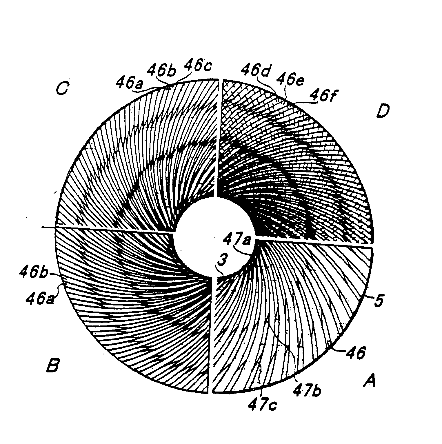
[0022] A dual layer of the acoustic elements, in an acute angle to normal to the driver, is aligned out-of-phase against the other layer, providing significant improvements to the characteristics of the acoustic diaphragm.

Problems solved by technology

However, in each of the applications described above, the construction and techniques employed did not take advantage of nor incorporate the advantages of the natural characteristics of layering as seen in a human eardrum.
Yet, in each of the applications described above, the construction and techniques employed did not take advantage of nor incorporate advantageous characteristics of a feather.

Method used


Image

  • Acoustic diaphragm
  • Acoustic diaphragm
  • Acoustic diaphragm

Examples


Embodiment Construction

[0064] An acoustic diaphragm is described herein. In the following description, numerous specific details are set forth by way of exemplary embodiments in order to provide a more thorough description of the present invention. It will be apparent, however, to one skilled in the art, that the present invention may be practiced without these specific details. In other instances, well-known features have not been described in detail so as not to obscure the invention. The preferred embodiments of the inventions are described herein in the Figures, Photographs and Detailed Description. Unless specifically noted, it is intended that the words and phrases in the specification and claims be given the ordinary and accustomed meaning as understood by those of ordinary skill in the applicable art or arts. If any other meaning is intended, the specification will specifically state that a special meaning is being applied to a word or phrase.

[0065] The present invention uses an alternative appro...


PUM


Abstract

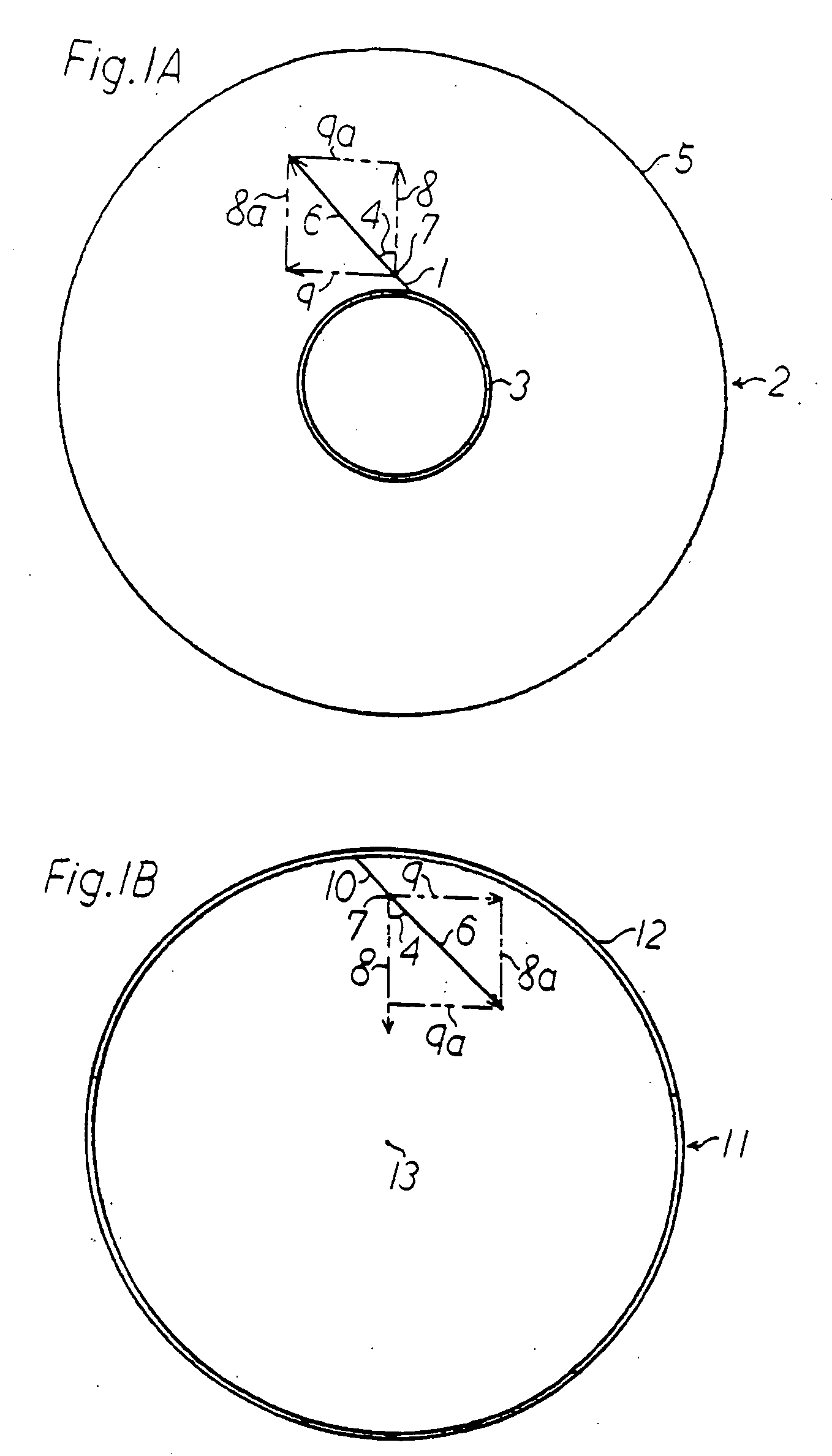
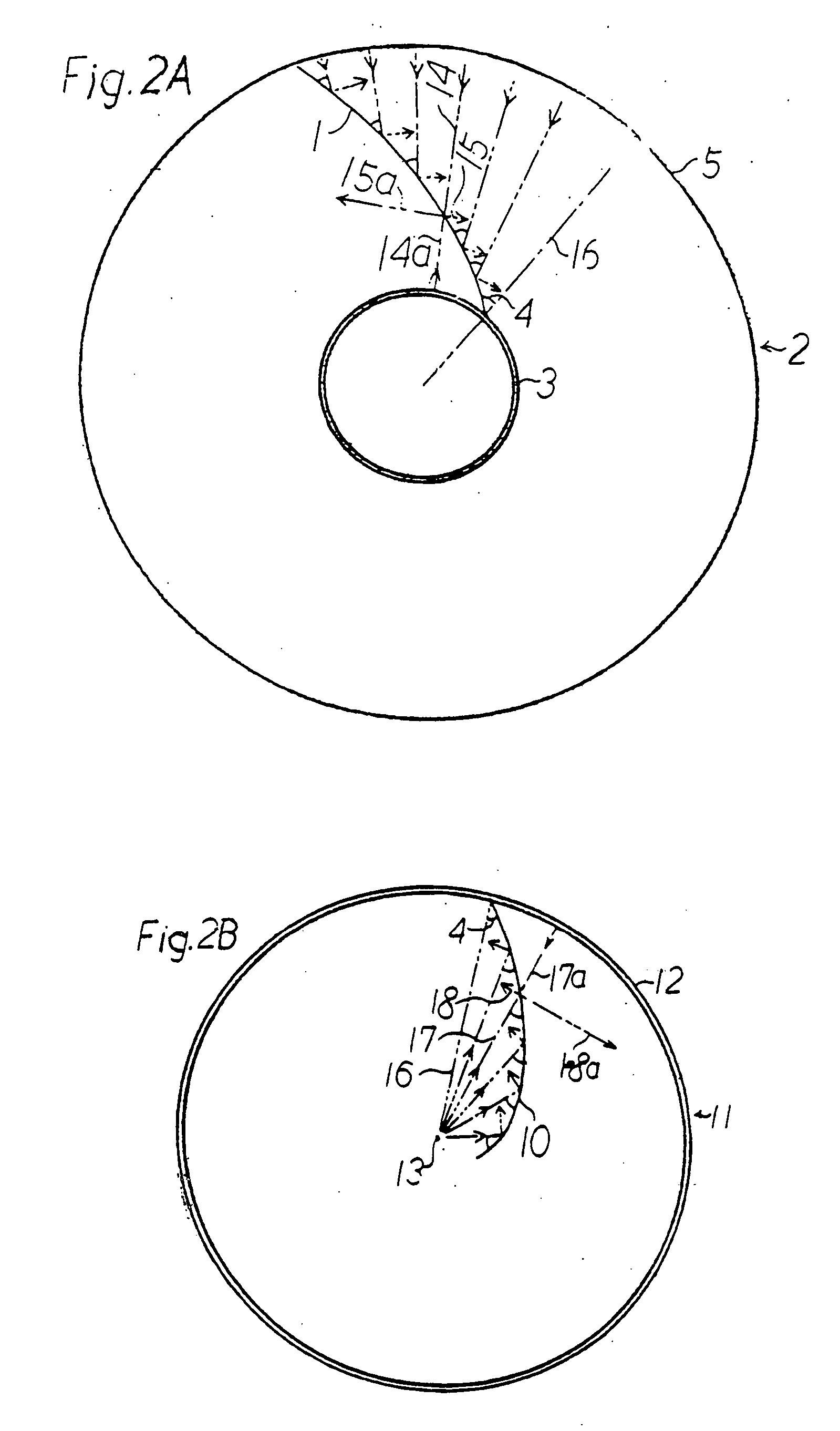
An acoustic diaphragm is disclosed having a plurality of acoustic elements supported by the diaphragm. In a preferred form, each element is coupled to a driver and extends radially at a uniform acute angle to a normal of the driver. In the preferred embodiment, a plural layer of the elements is arranged so that the direction of each element is out-of-phase relative to each other, preferably in the range of approximately ninety degree. An element is also supplemental to the conventional acoustic diaphragm. The improved acoustic diaphragm is used in electric acoustic and acoustic electric transducer systems having improved performance at wide frequency range.

Description

RELATED APPLICATIONS [0001] This application claims priority to U.S. Provisional application No. 60 / 586,065, filed Jul. 7, 2004.BACKGROUND OF THE INVENTION [0002] 1. Field of the Invention [0003] This invention relates to the field of electric to acoustic transducer systems and acoustic to electric transducer systems, and more specifically, to a system for an improved unique diaphragm having a plurality of acoustic elements supported by the diaphragm. [0004] 2. Description of the Related Art [0005] Common electric to acoustic transducer devices, and acoustic to electric transducer devices, are well documented in the following text and anthologies: Acoustic Engineering, Harry F. Olson, Ph.D., Van Norstrand Company, Inc., New Jersey, 1957 (Library of Congress catalogue card No. 57-8143) (hereinafter referred to as “Olson”); Loudspeakers, An anthology of articles on loudspeakers from the pages of the Journal of the Audio Engineering Society Vol. 1-Vol. 25 (1953-1977), 2nd Edition, Audi...

Claims


Application Information

Patent Timeline
IPC IPC(8): H04R25/00
CPCH04R7/10H04R7/122H04R7/125H04R2307/025H04R31/003H04R2307/021H04R7/127
Inventor NAGAOKA
Owner NAGAOKA
Learn More