Zirconia structural body and manufacturing method of the same

a technology of zirconia and structural body, which is applied in the direction of superimposed coating process, instruments, coatings, etc., can solve the problems of insufficient activation time of sensor, inability to reduce the thickness of various functional layers using this sheet laminating method, and inability to reduce the thickness of various functional layers. , to achieve the effect of reducing the manufacturing cost of zirconia structural body, shortening the film-forming time, and sufficient bonding strength

Inactive Publication Date: 2006-01-12
DENSO CORP
View PDF8 Cites 21 Cited by
  • Summary
  • Abstract
  • Description
  • Claims
  • Application Information

AI Technical Summary

Benefits of technology

[0010] In view of the above-described problems, the present invention has an object to provide a zirconia structural body excellent in reliability and also has an object to provide a manufacturing method of the same. More specifically, the present invention is applied to a zirconia structural body including a first electrode, a zirconia layer, and a second electrode which are successively laminated. The present invention has an object to provide a thin zirconia layer of the zirconia structural body. The present invention has an object to provide a zirconia structural body, when incorporated in a sensor, capable of improving the response of the sensor. The present invention has an object to provide a zirconia structural body which can be manufactured at low costs. The present invention has an object to provide a zirconia structural body which generates no cracks.

Problems solved by technology

However, using this sheet laminating method is not preferable to reduce the thicknesses of various functional layers, such as zirconia layers, other solid electrolyte layers, and gas diffusion layers.
The activation time of the sensor cannot be shortened sufficiently.
And, the sensor response will be dissatisfactory.
The above-described conventional spattering or thin-film forming method, although effective in improving sensor characteristics, requires high vacuum and takes a long time to form films of the sensor since this method depends on a vapor growth method.
Therefore, the method disclosed in the above-described prior art document 1 or 2 is dissatisfactory in productivity.
Accordingly, the manufacturing costs of the sensor will increase.
The reliability of the sensor will deteriorate.
Therefore, when the thin-film exhaust gas sensor uses the cubic zirconia layer to prevent phase transformation, cracks will generate due to a thermal expansion coefficient difference between the alumina substrate and the cubic zirconia layer.
The reliability of the sensor will deteriorate.

Method used


Image

  • Zirconia structural body and manufacturing method of the same
  • Zirconia structural body and manufacturing method of the same
  • Zirconia structural body and manufacturing method of the same

Examples


Embodiment Construction

[0038] A preferred embodiment of the present invention will be explained hereinafter with reference to attached drawings.

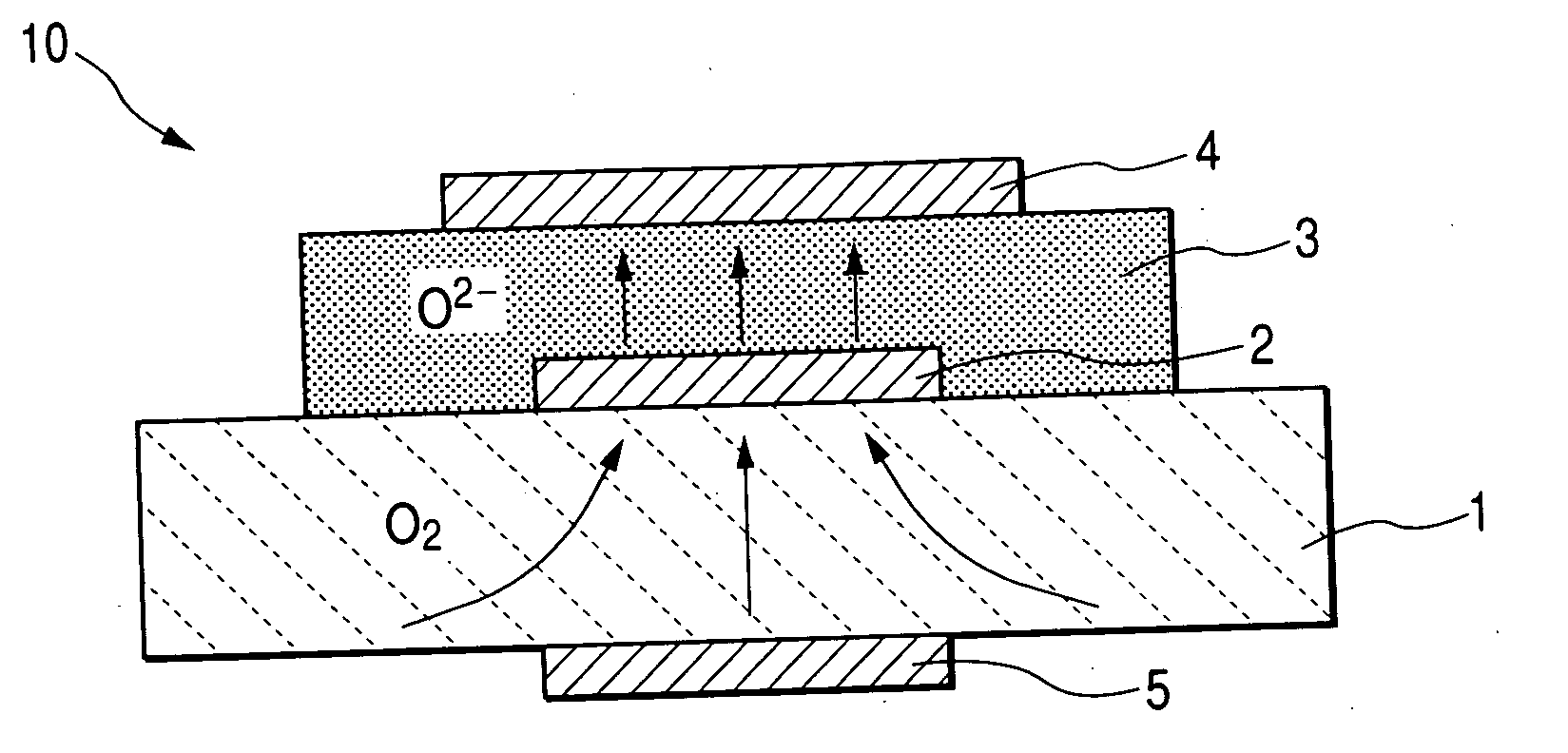
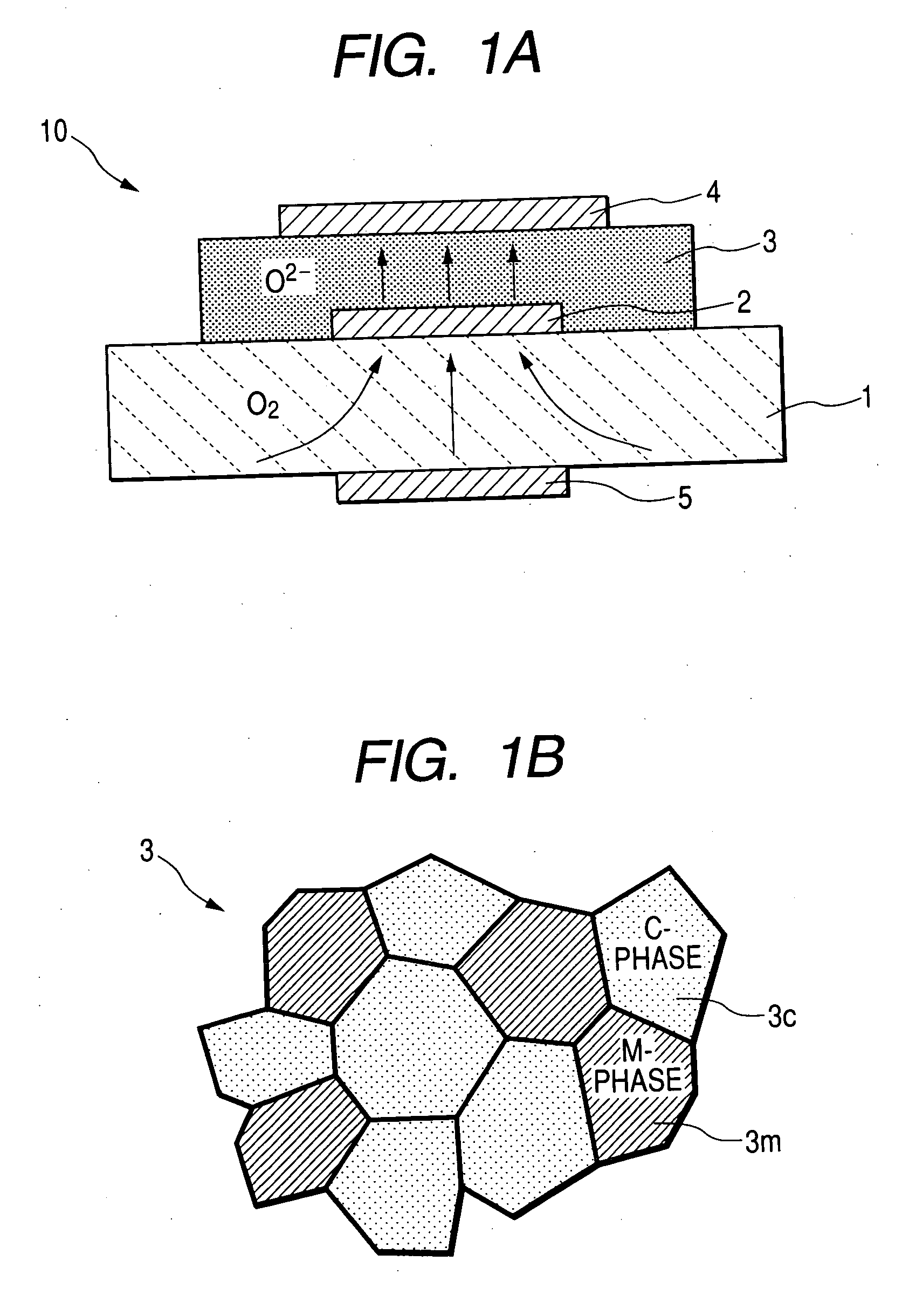
[0039]FIG. 1A is a cross-sectional view schematically showing a zirconia structural body in accordance with a preferred embodiment of the present invention.

[0040] A zirconia structural body 10 shown in FIG. 1A is an exhaust gas sensor for an automotive vehicle which includes a zirconia layer as a solid electrolyte. According to the zirconia structural body 10 shown in FIG. 1A, a first electrode 2, a zirconia layer 3, and a second electrode 4 are successively laminated on one surface of a substrate 1.

[0041] The substrate 1 shown in FIG. 1A is made of alumina (Al2O3) having excellent thermal conductivity. The substrate 1 is a porous substrate allowing diffusion of oxygen (O2) gas. For example, the gas diffusibility in the substrate 1 is adjustable by controlling the porosity of an alumina material in the sintering process.

[0042] The zirconia layer 3 (i.e. solid ...


PUM

PropertyMeasurementUnit
average grain diameteraaaaaaaaaa
thicknessaaaaaaaaaa
velocityaaaaaaaaaa

Abstract

A zirconia structural body includes a substrate having one surface on which a first electrode, a zirconia layer, and a second electrode are successively laminated. The zirconia layer is a bonded body of mixture consisting of monoclinic zirconia crystal grains and cubic zirconia crystal grains.

Description

CROSS-REFERENCE TO RELATED APPLICATION [0001] This application is based upon and claims the benefit of priority from earlier Japanese Patent Application No. 2004-199615 filed on Jul. 6, 2004 so that the description of which is incorporated herein by reference. BACKGROUND OF THE INVENTION [0002] The present invention relates to a zirconia structural body including a substrate having one surface on which a first electrode, a zirconia layer, and a second electrode are successively laminated, and also relates to a method for manufacturing this zirconia structural body. [0003] The Japanese patent application laid-open No. 6-201642(1994) corresponding to U.S. Pat. No. 5,480,535 (hereinafter referred to as prior art document 1) or the Japanese patent application laid-open No. 7-55765 (1995) corresponding to U.S. Pat. No. 5,480,535 (hereinafter referred to as prior art document 2) discloses a zirconia structural body including a substrate having one surface on which a first electrode, a zir...

Claims


Application Information

Patent Timeline
Patent Type & Authority Applications(United States)
IPC IPC(8): C04B35/48
CPCC04B41/009C23C28/3455C04B41/90C04B2111/0025C23C24/04G01N27/4071C04B41/52C23C28/322C04B41/4543C04B41/4572C04B41/5122C04B41/5042C04B35/10
Inventor SONE, MASAHIROTOTOKAWA, MASASHI
Owner DENSO CORP
Why Eureka
Try Eureka