
Formal methods for test case generation

a test case and form factor technology, applied in the field of form factor test case generation, can solve the problems of high test coverage, high test cost, and inability to generate test cases, and achieve the effect of reducing the development cost of the system and rapid test case generation

Active Publication Date: 2006-01-12
SRI INTERNATIONAL
View PDF0 Cites 84 Cited by
  • Summary
  • Abstract
  • Description
  • Claims
  • Application Information

AI Technical Summary

Benefits of technology

The invention provides a way to quickly generate test cases that cover a system's requirements. This automated method reduces development costs and allows for extending existing tests to new coverage targets. The method also allows for parallel searching and analysis of all undiscovered target goals. The system uses a model of the system and a collection of test cases to check the coverage metric. The method can be used with any tool that solves constraints and model checkers are discussed as an example. Overall, the invention provides a faster and more efficient way to generate test cases for a system.

Problems solved by technology

Testing to high coverage is enormously expensive.
Performing tests and evaluating test outcomes can be automated to a considerable degree, but generating test cases still is a largely a time consuming manual process.
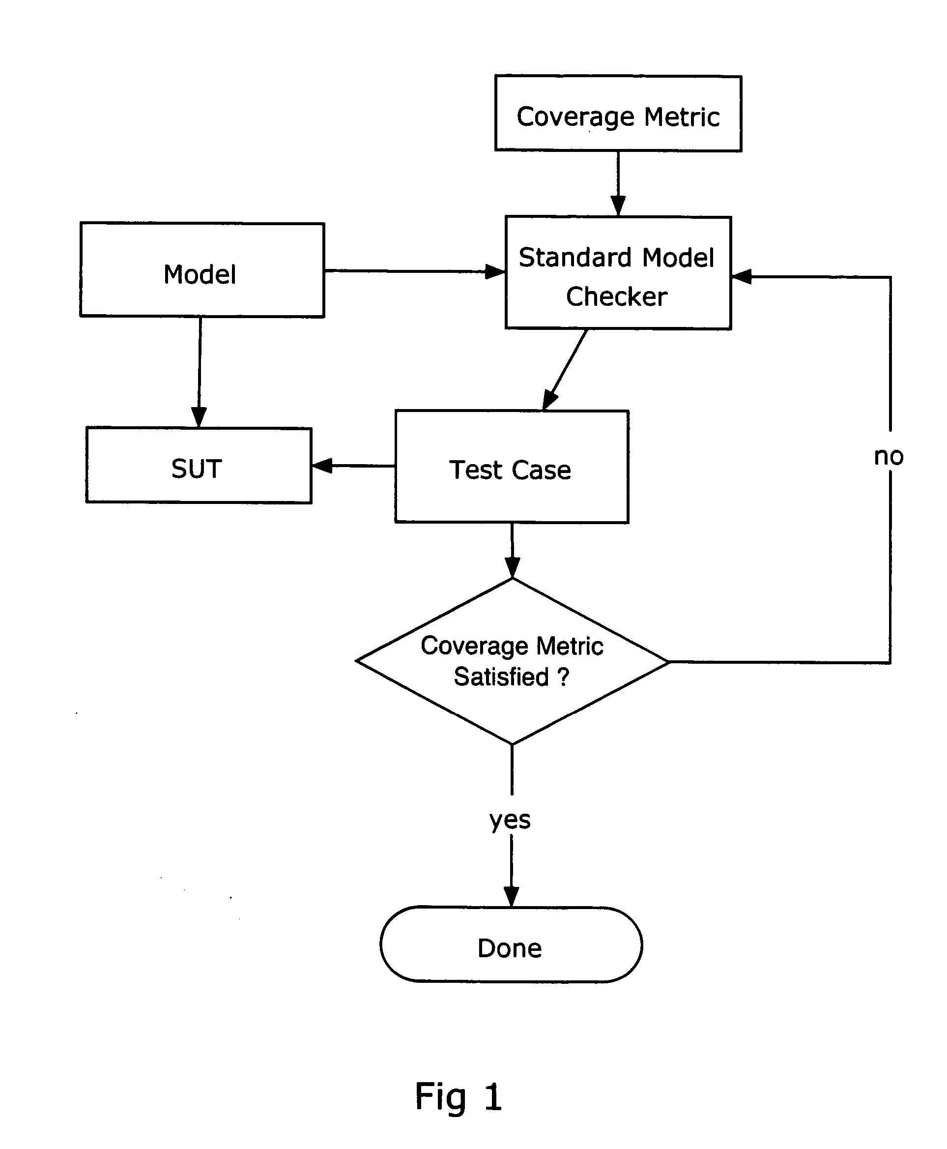
Because each test is generated separately, each of them restarts the SUT (which can make the test expensive to perform), and the set of tests generated by this approach contains much redundancy (e.g., many tests start the same way).
This is inefficient, both in generating tests, and in executing them.
Furthermore, the model checker or other method may be unable to solve the constraint satisfaction problems for targets whose tests require many steps from an initial state.
Restricted to explicit-state model checking, these tour-based approaches are unsuited to achieving coverage goals (e.g., MC / DC; See K. Hayhurst, D. Veerhusen, J. Chilenski, and L. Rierson. A Practical Tutorial on Modified Condition / Decision Coverage.

Method used


Image

  • Formal methods for test case generation
  • Formal methods for test case generation
  • Formal methods for test case generation

Examples


Embodiment Construction

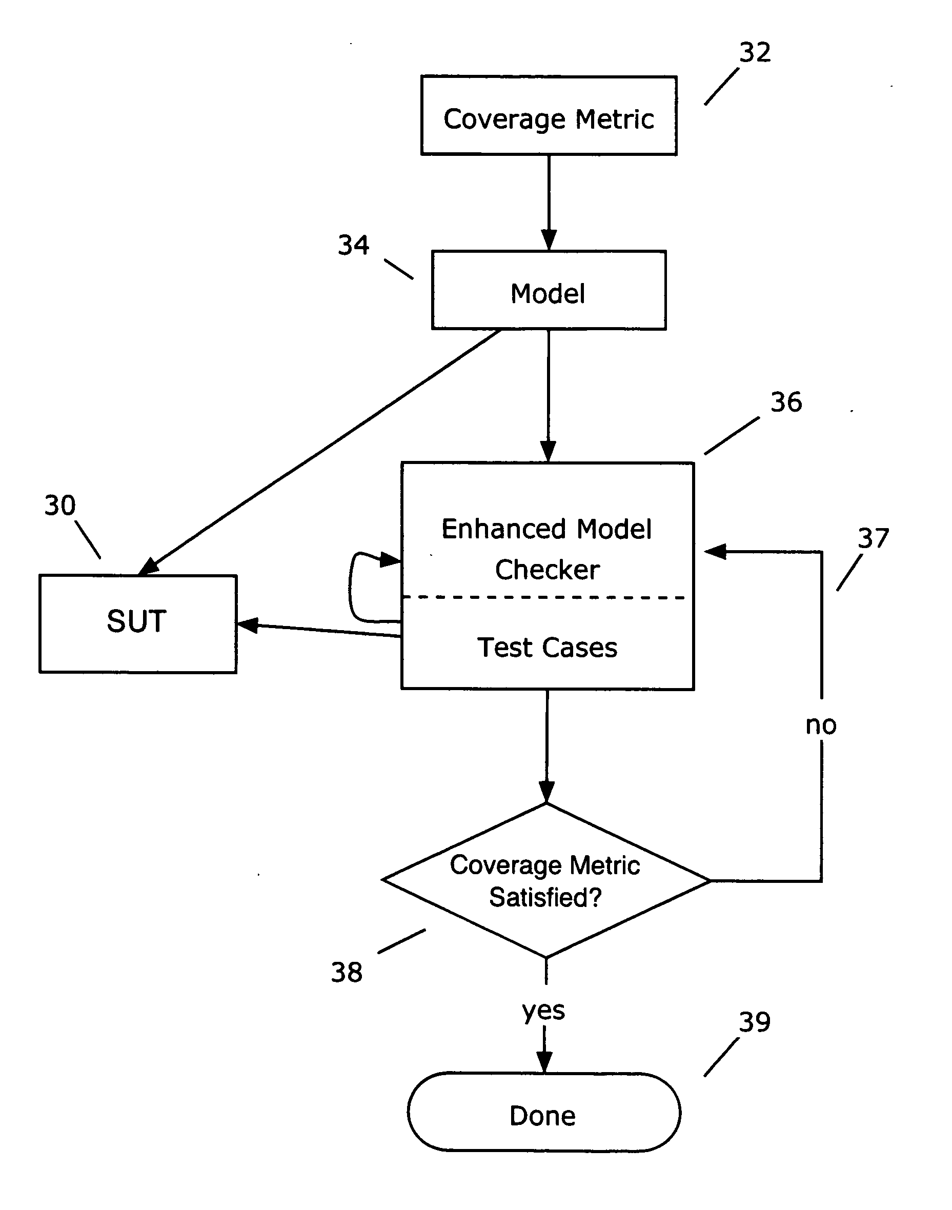
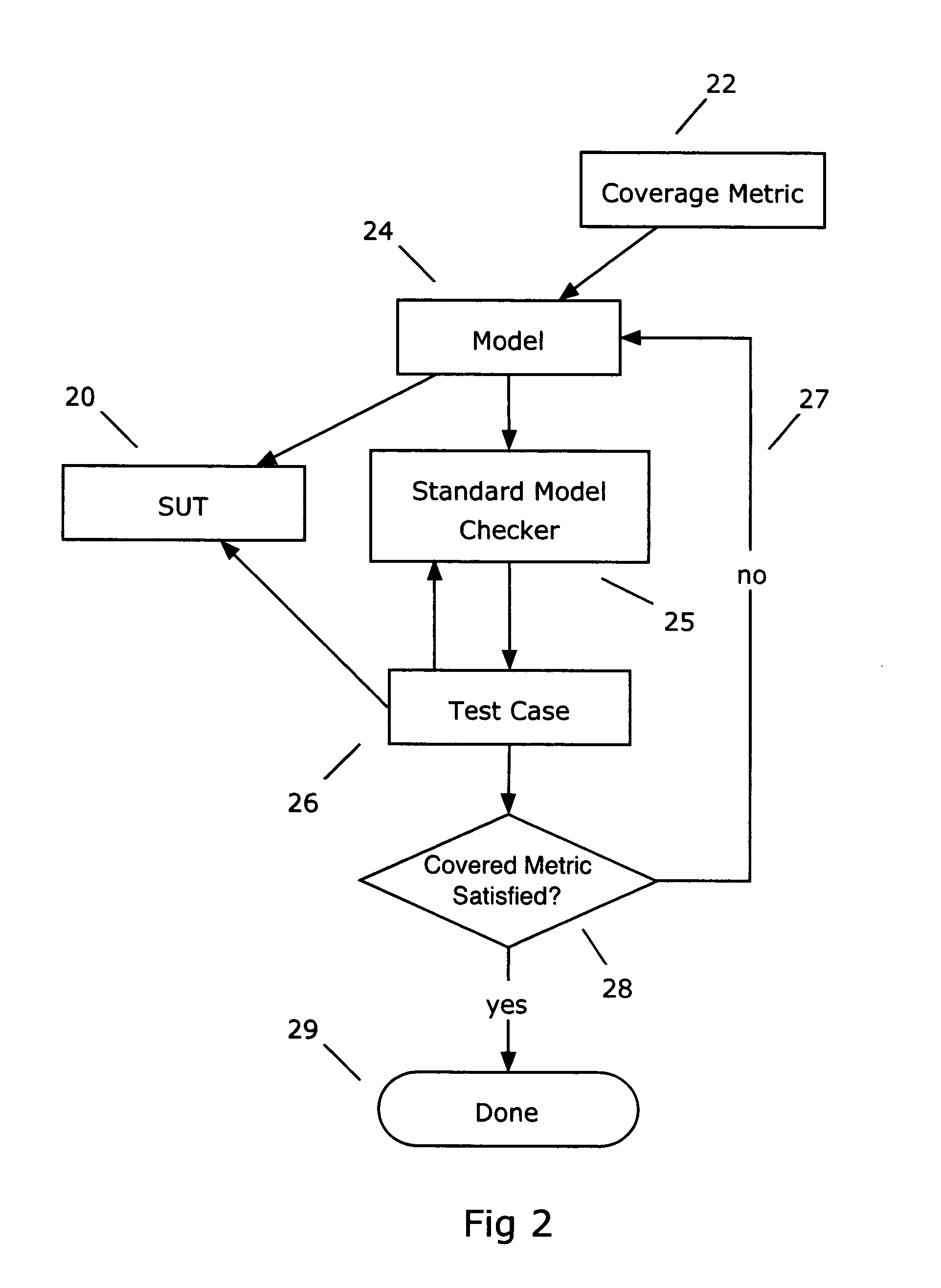
[0023] Referring to FIG. 2, the inventive approach provides a method for generating tests for a system under test (SUT) 20 that satisfy a coverage metric 22 by generating a model 24 of the SUT; generating a first test case 26 with respect to the model; adding the first test case to a collection of test cases; checking the coverage metric 28 over the collection and if the coverage metric is not satisfied 27; reducing the model; and generating a second test case with respect to the reduced model. Rather than returning to the initial state and revisiting all intermediate states already visited, the new test case is extended from the last visited state.

[0024] The path 27 in FIG. 2 represents modification of the model in two distinct ways: slicing and extension. As regards any given set of test targets, slicing eliminates those parts of the model that cannot contribute to the satisfaction of the coverage goals. Slicing is performed internally each time the set of outstanding goals is re...


PUM


Abstract

The invention relates to the use of model checkers to generate efficient test sets for hardware and software systems. The method provides for extending existing tests to reach new coverage targets; searching *to* some or all of the uncovered targets in parallel; searching in parallel *from* some or all of the states reached in previous tests; and slicing the model relative to the current set of coverage targets. The invention provides efficient test case generation and test set formation. Deep regions of the state space can be reached within allotted time and memory. The approach has been applied to use of the model checkers of SRI's SAL system and to model-based designs developed in Stateflow. Stateflow models achieving complete state and transition coverage in a single test case are reported.

Description

GOVERNMENT FUNDING [0001] This application was made in part with government support under contract number NAS1-00079 awarded by NASA Langley Research Center; this application was also made in part with government support under contract number CCR-00-86096 awarded by the National Science Foundation. The Government has certain rights in this invention.RELATED APPLICATIONS [0002] Not applicable. BACKGROUND [0003] Testing is the dominant method for finding bugs in computer software and hardware. When combined with methods to measure the amount of coverage achieved, it is also the dominant method for assessing when the software or hardware concerned is good enough for release. Testing to high coverage is enormously expensive. For example, more than half the development costs in avionics systems are spent on verification and validation activities, and testing is a substantial part of verification and validation. In hardware and software companies, more than half the entire technical staff...

Claims


Application Information

Patent Timeline
Patent Type & Authority Applications(United States)
IPC IPC(8): G06F9/44
CPCG06F11/3684
Inventor RUSHBY, JOHN M.DE MOURA, LEONARDO MENDONGAHAMON, GREGOIRE
Owner SRI INTERNATIONAL
Learn More