Mounting a turbine nozzle on a combustion chamber having CMC walls in a gas turbine

a technology of combustion chamber and turbine nozzle, which is applied in the direction of machines/engines, liquid fuel engines, lighting and heating apparatus, etc., can solve the problems of resolving the problem of assembling together parts made of materials (cmc and metal)

Active Publication Date: 2006-01-19
SN DETUDE & DE CONSTR DE MOTEURS DAVIATION S N E C M A
View PDF12 Cites 107 Cited by
  • Summary
  • Abstract
  • Description
  • Claims
  • Application Information

AI Technical Summary

Benefits of technology

[0006] An object of the invention is to provide an effective mount for a turbine nozzle on a combustion chamber having walls made of CMC, serving in particular to reduce the number of parts needed, thus saving weight, and also simplifying structure.
[0008] Making the turbine nozzle out of CMC and connecting it to the combustion chamber by brazing achieves a very significant saving in weight, compared with a turbine nozzle made of metal, because of the lower density of CMCs, and it also enables the problem of continuity between the combustion chamber and the nozzle to be solved more effectively.
[0009] Advantageously, the downstream portions of the inner and outer walls of the combustion chamber are extended to the downstream end of the turbine nozzle so as form the inner and outer walls of the flow path to which the airfoils are connected by brazing. Thus, the extensions of the combustion chamber walls act in simple manner to guarantee continuity and sealing for the gas stream flowing through the turbine nozzle.
[0022] According to an advantageous feature of the invention, means other than the linking members are provided to prevent the turbine nozzle from turning relative to at least one of the metal shrouds so as to avoid turning forces induced on the airfoils of the nozzle by the gas stream coming from the chamber being taken up by the linking members.

Problems solved by technology

Nevertheless, difficulties remain relating to assembling together parts made of materials (CMC and metal) that have different coefficients of thermal expansion.

Method used


Image

  • Mounting a turbine nozzle on a combustion chamber having CMC walls in a gas turbine
  • Mounting a turbine nozzle on a combustion chamber having CMC walls in a gas turbine
  • Mounting a turbine nozzle on a combustion chamber having CMC walls in a gas turbine

Examples


Embodiment Construction

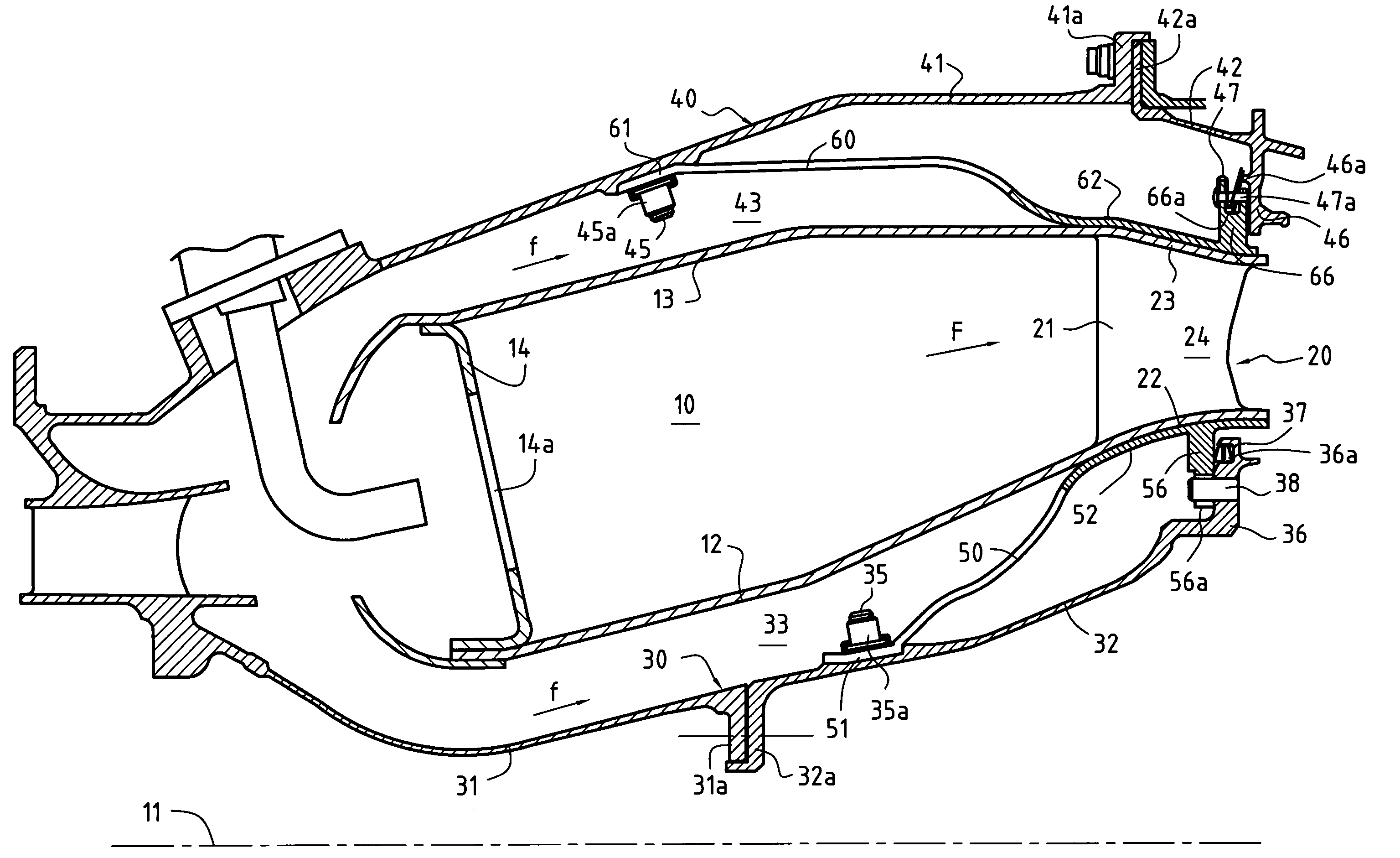
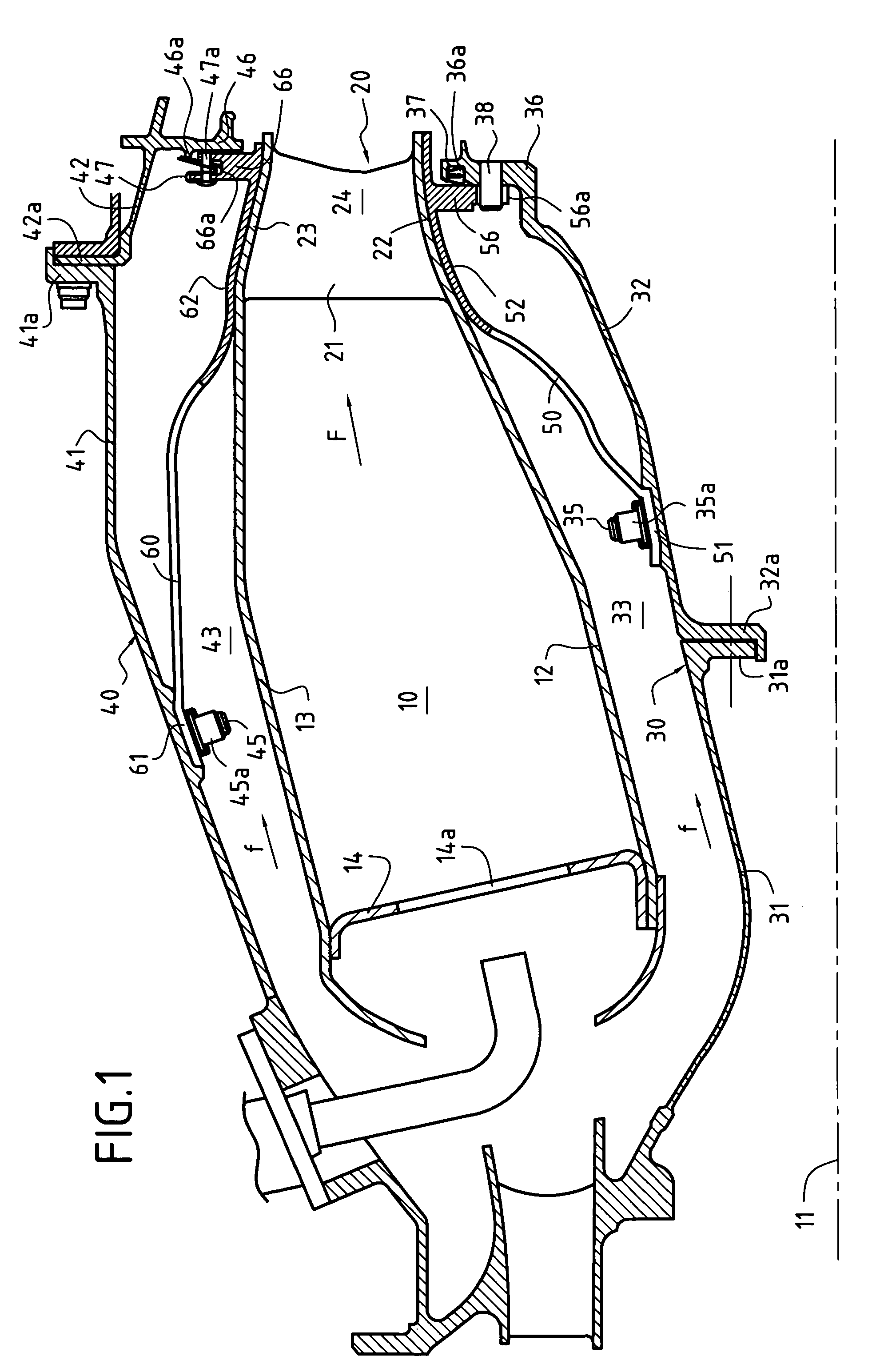
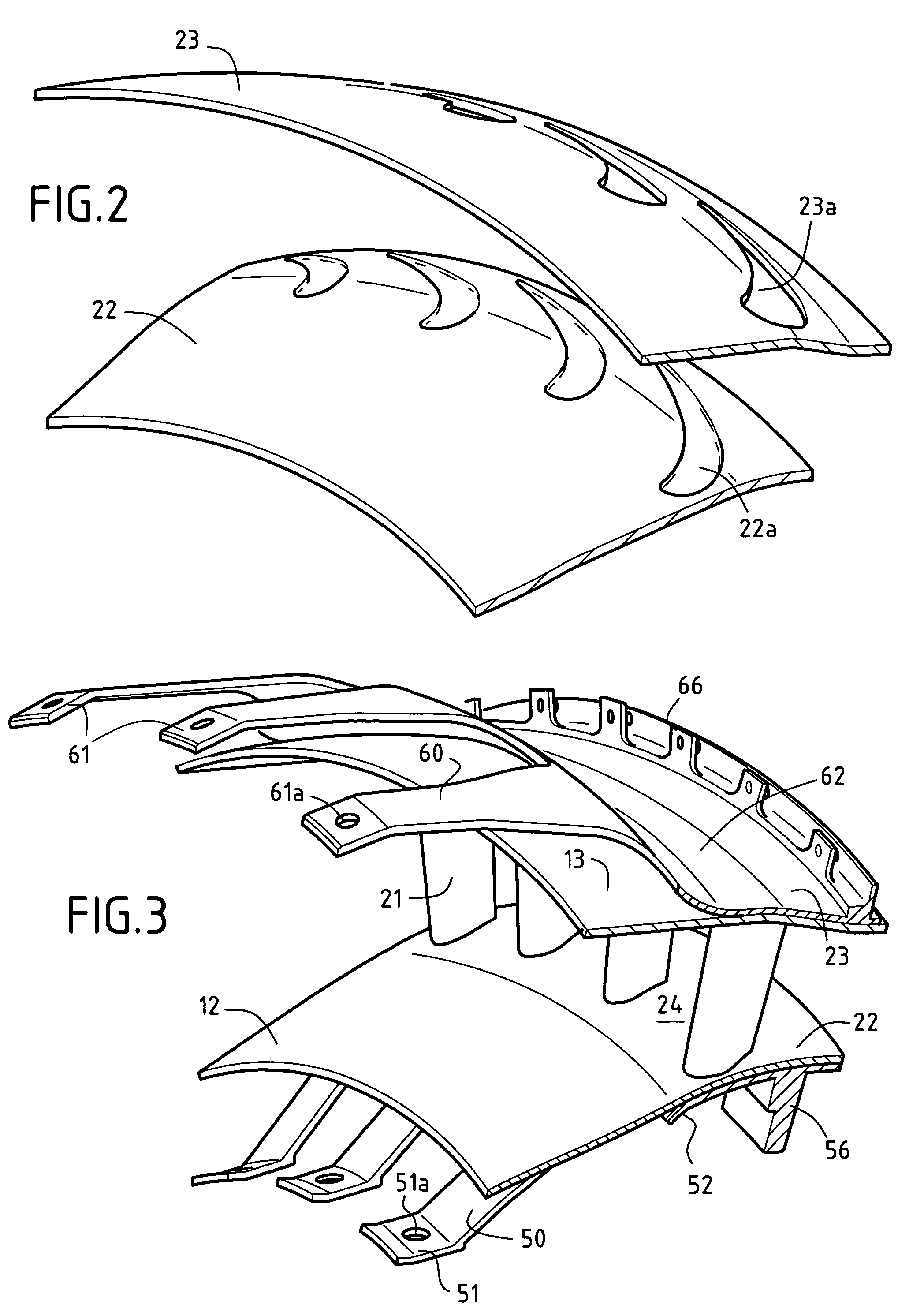
[0031]FIG. 1 is an axial half-section view showing a portion of a gas turbine comprising a circular combustion chamber 10, a high pressure (HP) turbine nozzle 20 situated downstream from the combustion chamber 10 and connected directly thereto, a metal casing comprising inner and outer metal shrouds 30 and 40, and inner and outer linking tabs 50 and 60 holding the chamber and nozzle assembly 10 and 20 in the metal casing. In the description below, the terms “upstream” and “downstream” are used with reference to the flow direction (arrow F) of the gas stream coming from the chamber 10.

[0032] The combustion chamber 10 is defined by an inner annular wall 12 and an outer annular wall 13 on the same axis 11, and by an end wall 14 fastened to the walls 12 and 13. In well-known manner, the end wall 14 presents openings 14a distributed around the axis 11 to house injectors enabling fuel and oxidizer to be injected into the chamber 10. The walls 12 and 13 of the chamber 10 are made of CMC, ...


PUM


Abstract

The gas turbine comprises an annular combustion chamber having inner and outer walls made of ceramic matrix composite material, and a high pressure turbine nozzle secured to a downstream end of the combustion chamber and comprising a plurality of stationary airfoils extending between the inner and outer walls of an annular flow path through the nozzle for the gas stream coming from the combustion chamber. The turbine nozzle is made of ceramic matrix composite material and it is connected to the downstream end of the combustion chamber by brazing.

Description

BACKGROUND OF THE INVENTION [0001] The invention relates to gas turbines, and more particularly to mounting a turbine nozzle on a combustion chamber having walls made of ceramic matrix composite (CMC) material. The fields of application of the invention are industrial gas turbines and also turbojets and turboprops for airplanes. [0002] CMCs have been proposed in making the walls of gas turbine combustion chambers because of the thermostructural properties of CMCs, i.e. their ability to conserve good mechanical properties at high temperatures. The requirements to improve efficiency and to reduce emissions of polluting species both lead to seeking an ever-higher combustion temperature. [0003] Document FR 2 825 787 shows an annular combustion chamber made of CMC that is mechanically connected to a high pressure turbine nozzle (the inlet stage of the turbine). The turbine nozzle is made up of stationary vanes comprising platforms with airfoils extending between platforms. The platforms ...

Claims


Application Information

Patent Timeline
Patent Type & Authority Applications(United States)
IPC IPC(8): F23R3/42F01D9/02F01D9/04F23R3/00F23R3/60
CPCF01D9/023F01D9/044Y02T50/675F23R3/60Y02T50/672F05D2300/6033Y02T50/60F02C7/20
Inventor AUMONT, CAROLINECONETE, ERICDE SOUSA, MARIOHERNANDEZ, DIDIERHABAROU, GEORGES
Owner SN DETUDE & DE CONSTR DE MOTEURS DAVIATION S N E C M A
Why Eureka
Try Eureka