Dynamic balance testing machine

a testing machine and dynamic balance technology, applied in the direction of measuring devices, structural/machine measurement, instruments, etc., can solve the problems of difficult automation, high cost, and inability to correct rotational imbalance, and achieve accurate measurement, easy change of machine setup, and increased machine reliability

Inactive Publication Date: 2006-01-19
NAGAHAMA SEISAKUSHO
View PDF3 Cites 12 Cited by
  • Summary
  • Abstract
  • Description
  • Claims
  • Application Information

AI Technical Summary

Benefits of technology

[0025] Where the midst of a duration in which the sensor light is interrupted by the crank pin is utilized as a reference signal, the unbalance of the test piece can be measured without being influenced by variations in size of the crank pin or the difference in size toward half-diameter from the rotational axial center of the crank pin, so that the reliability of the machine is increased.
[0026] According to the present invention having the abovementioned arrangements, an unbalance of especially an asymmetrical crank shaft can be accurately measured. In addition, such a dynamic balance testing machine can be provided that the set-up of the machine can easily be changed.

Problems solved by technology

It is unsatisfactory to correct a rotational unbalance of an asymmetrical crank shaft as a single body, but it is necessary to correct a rotational unbalance of an asymmetrical crank shaft fitted with a piston and a connecting rod.
However, according to this method, attaching and removing the dummy weight is often manually carried out, and automation thereof is difficult.
In addition, if an automatic dummy weight attaching and removing device is to produce, such a device has a disadvantage in its complicated structure and will be very expensive as a whole.
Further, attachment and removal of the dummy weight takes some time, and therefore this method has another disadvantage that the measurement time of a rotational unbalance of one crank shaft, so-called a cycle time, becomes excessive.
However, this prior art has a problem that, since the dummy shaft is mechanically connected to the rotational driving device of the crank shaft, much time is required for adjusting pulleys, gears and the like in the mechanical connecting portion and variations in precision, accuracy, weight distribution and the like of the parts in the connecting portion tend to affect the measurement accuracy.
In addition, this device has another problem that it is difficult to change the set-up of the device when an unbalance of each of plural crank shafts with many kinds are measured.
However, this art has a problem that, since the free moment of the crank shaft is several ten times to several hundred times as large as the unbalance of the crank shaft to be measured, and removing the vibration due to such a large free moment by electrical compensation results in lowering in the measurement accuracy.
Further, there is another problem that calibration (revision) has to often be carried out in order to use such a device for a long time.

Method used


Image

  • Dynamic balance testing machine
  • Dynamic balance testing machine
  • Dynamic balance testing machine

Examples


Embodiment Construction

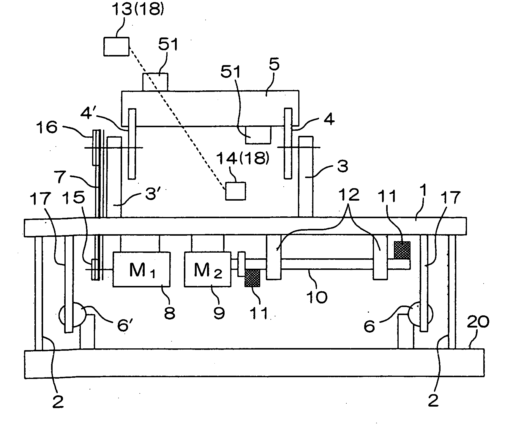
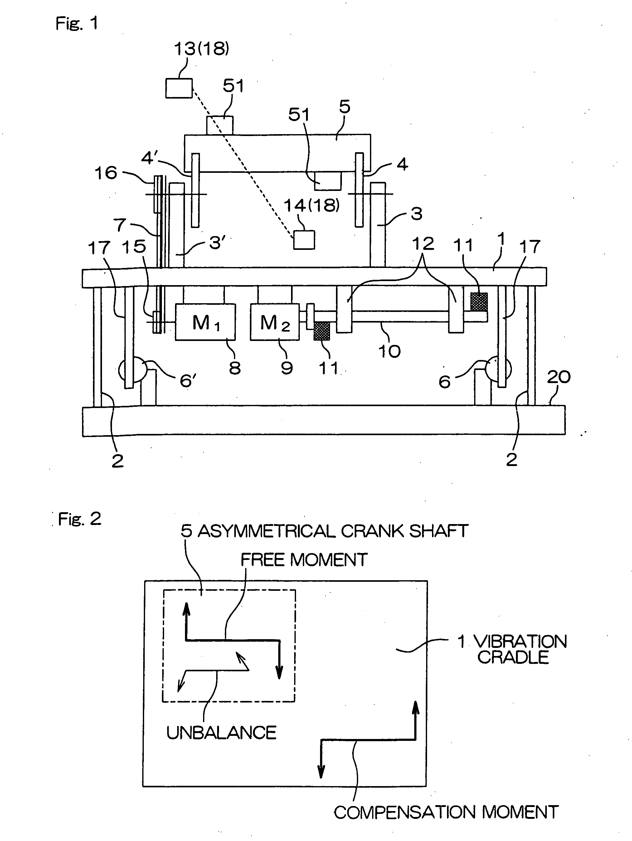
[0034] Referring to FIG. 1, in a dynamic balance testing machine according to this embodiment, a vibration cradle 1 is held by, for example, four supporting springs 2 vertically set up on a base 20 so as to be vibrated. That is, the vibration cradle 1 is provided in such a manner that it can be vibrated depending on the unbalance amount of a test piece when it is measured. On the vibration cradle 1, a pair of supports 3, 3′ are vertically set up. The supports 3, 3′ rotatably support a pair of bearing rollers 4, 4′, respectively. With two pairs of bearing supports 4, 4′, an asymmetrical crank shaft 5 as a test piece is supported at the both ends thereof.

[0035] A drive motor 8 is provided, for example, on the lower surface of the vibration cradle 1. The rotational force of the drive motor 8 is transmitted to one bearing roller pair 4′ by a pulley 15, a driving belt 7 and a pulley 16. In other words, the bearing roller pair 4′ is rotated by the drive motor 8. With the rotation of the ...


PUM


Abstract

A dynamic balance testing machine is provided with mechanical arrangements for canceling out a free moment of an asymmetrical crank shaft and capable of accurately measuring a rotating unbalance of the asymmetrical crank shaft. A compensation rotational shaft 10 having a compensation weights 11 for canceling out a free moment of a crank shaft 5 as a test piece is provided on a vibration cradle 1. The compensation rotational shaft 10 is rotated by a synchronous motor 9 other than a synchronous motor 8 for rotating the crank shaft 5. The synchronous motor 9 is rotated based on a reference signal detected by an optical sensor 18 (13, 14) in such a manner that the synchronous motor 9 is synchronously rotated with the rotation of the crank shaft.

Description

FIELD OF THE INVENTION [0001] The present invention relates to a dynamic balance testing machine, and more particularly to a dynamic balance testing machine for measuring an unbalance of an asymmetrical crank shaft. BACKGROUND OF THE INVENTION [0002] Crank shafts constituting a main part of an internal combustion engine include so-called asymmetrical crank shafts. Typical asymmetrical crank shafts are, e.g., 3-cylinder or 6-cylinder of V-type engines. The weight distribution of such an asymmetrical crank shaft is not symmetrical relative to its rotational axial center and an asymmetrical crank shaft as a single body has a moment (which is called a free moment) due to its predetermined dynamic unbalance. In case of measuring a rotational unbalance of such an asymmetrical crank shaft, it is necessary to resourcefully treat the abovementioned free moment, because a large vibration is occurred due to the free moment. [0003] It is unsatisfactory to correct a rotational unbalance of an as...

Claims


Application Information

Patent Timeline
Patent Type & Authority Applications(United States)
IPC IPC(8): G01M1/30G01M1/16G01M1/20G01M1/24
CPCG01M1/24
Inventor KYOGOKU, YOSHIAKI
Owner NAGAHAMA SEISAKUSHO
Why Eureka
Try Eureka