Method and components for implementing EMC shielded resonance damping

a shielded resonance and electromagnetic compatibility technology, applied in the field of data processing, can solve problems such as the lack of decoupling capacitors in det arrangements and resonances of damping boards

Inactive Publication Date: 2006-01-19
IBM CORP
View PDF13 Cites 5 Cited by
  • Summary
  • Abstract
  • Description
  • Claims
  • Application Information

AI Technical Summary

Benefits of technology

[0008] Principal aspects of the present invention are to provide a method and components for implementing EMC shielded resonance damping of a printed circuit board. Other important aspects of the present in

Problems solved by technology

Presently, there is a problem with dampening board resonances that occur between the principal planes in a circuit board.
Dissipative edge termination (DET) arrangements have been developed that essentially place

Method used


Image

  • Method and components for implementing EMC shielded resonance damping
  • Method and components for implementing EMC shielded resonance damping
  • Method and components for implementing EMC shielded resonance damping

Examples


Embodiment Construction

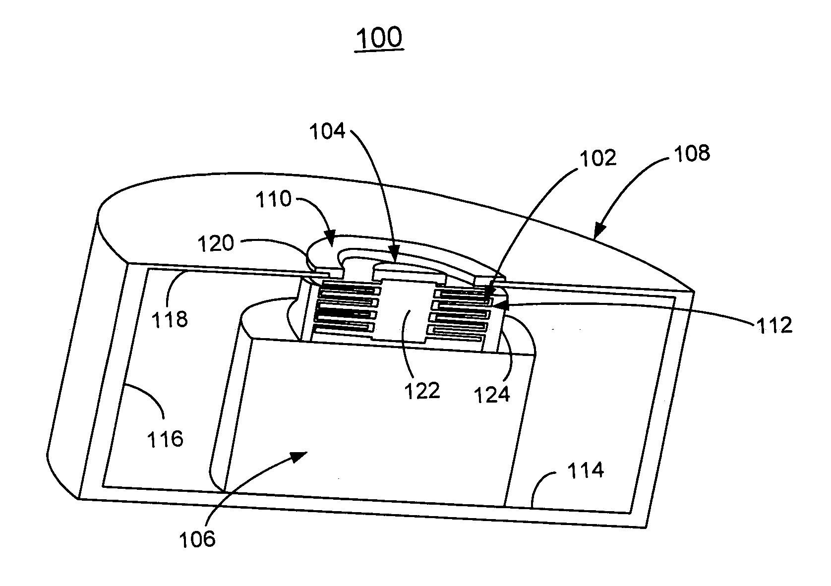
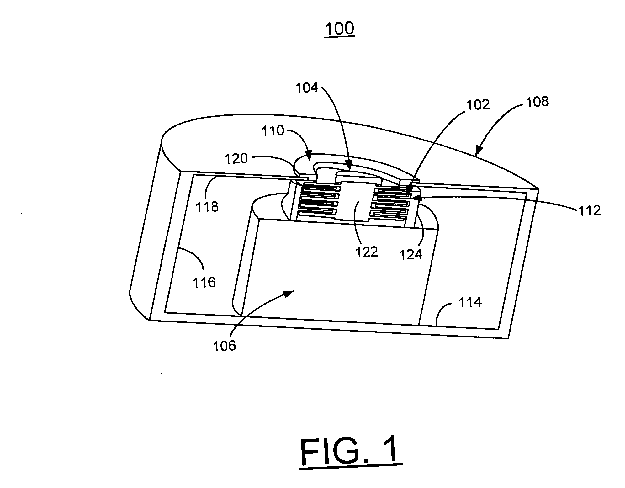
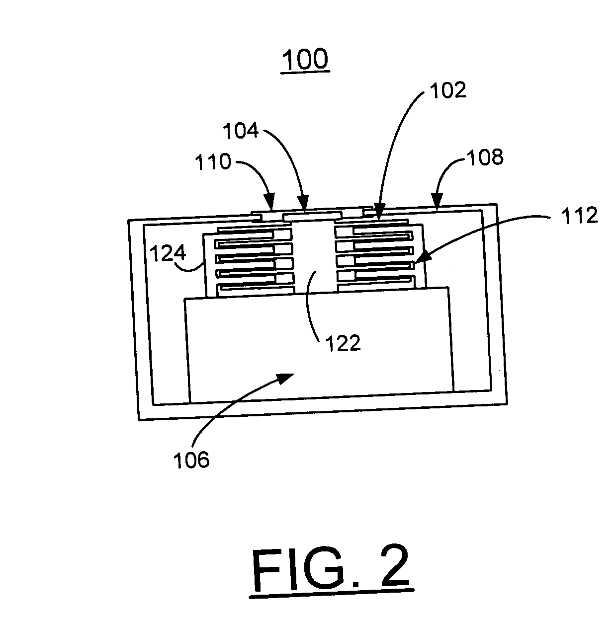
[0017] Having reference now to the drawings, in FIGS. 1, 2, and 3, there is shown an exemplary EMC shielded resonance damping component generally designated by the reference character 100 including surface mounted device (SMD) packaging in accordance with one preferred embodiment. EMC shielded resonance damping component 100 is arranged to be implemented in a smaller package than a conventional 0805 size package.

[0018] As shown in FIGS. 1 and 2, EMC shielded resonance damping component 100 contains a series capacitor generally designated by the reference character 102 connected between a first generally centrally located coaxial pad 104 and one side of a resistor 106. The resistor 106 is formed of a resistive bulk material. The capacitor 102 and resistor 106 are contained within a shielded enclosure 108.

[0019] A second coaxial via pad 110 providing a shield connection surrounds the first coaxial pad 104 and is connected to the shielded enclosure 108. The coaxial via pad 110 is clo...


PUM


Abstract

A method and components are provided for implementing EMC shielded resonance damping of a printed circuit board. The EMC shielded resonance damping component includes a capacitor and resistor formed in series combination and contained within a shielded enclosure. A pair of coaxial pads is provided for connection to the printed circuit board. The series combination of the capacitor and resistor is connected between a first pad of a pair of coaxial pads and an interior wall of the shielded enclosure. The shielded enclosure provides a return current path to a second pad of the pair of coaxial pads through the series components.

Description

FIELD OF THE INVENTION [0001] The present invention relates generally to the data processing field, and more particularly, relates to a method and components for implementing electromagnetic compatibility (EMC) shielded resonance damping. DESCRIPTION OF THE RELATED ART [0002] Presently, there is a problem with dampening board resonances that occur between the principal planes in a circuit board. Traditionally, for certain intermediate frequency ranges, decoupling capacitors are added into a grid pattern in an attempt to dampen the resonances and additionally to provide some local storage for placed modules. [0003] Since these decoupling capacitors are mainly reactive components, a series resistance of about 5 ohms or less is needed to dissipate the resonant energy. [0004] Dissipative edge termination (DET) arrangements have been developed that essentially place 0805 size resistors at the edge of the board periphery, but known DET arrangements lack the decoupling capacitors that are ...

Claims


Application Information

Patent Timeline
IPC IPC(8): H05K9/00H05K1/02
CPCH05K1/023H05K1/0231H05K2201/1053H05K2201/10022H05K2201/09809
Inventor GILLILAND, DON ALANWURTH, DENNIS JAMES
Owner IBM CORP
Why Eureka
Try Eureka