Multi-axial electrically conductive cable with multi-layered core and method of manufacture and use

Inactive Publication Date: 2006-01-19
GENERAL ELECTRIC CO
View PDF14 Cites 31 Cited by
  • Summary
  • Abstract
  • Description
  • Claims
  • Application Information

AI Technical Summary

Problems solved by technology
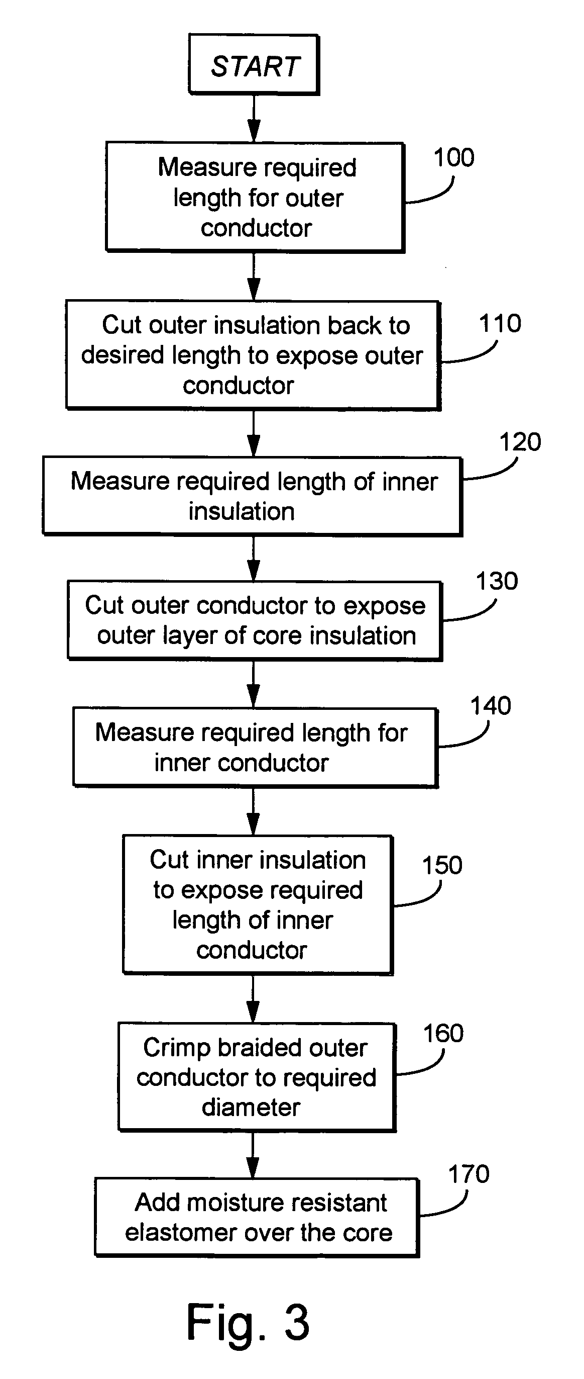
These fixed diameter sizes create difficulties with manufacturing costs and flexibility and with inventory control, because

Method used


Image

  • Multi-axial electrically conductive cable with multi-layered core and method of manufacture and use
  • Multi-axial electrically conductive cable with multi-layered core and method of manufacture and use
  • Multi-axial electrically conductive cable with multi-layered core and method of manufacture and use

Examples


Embodiment Construction

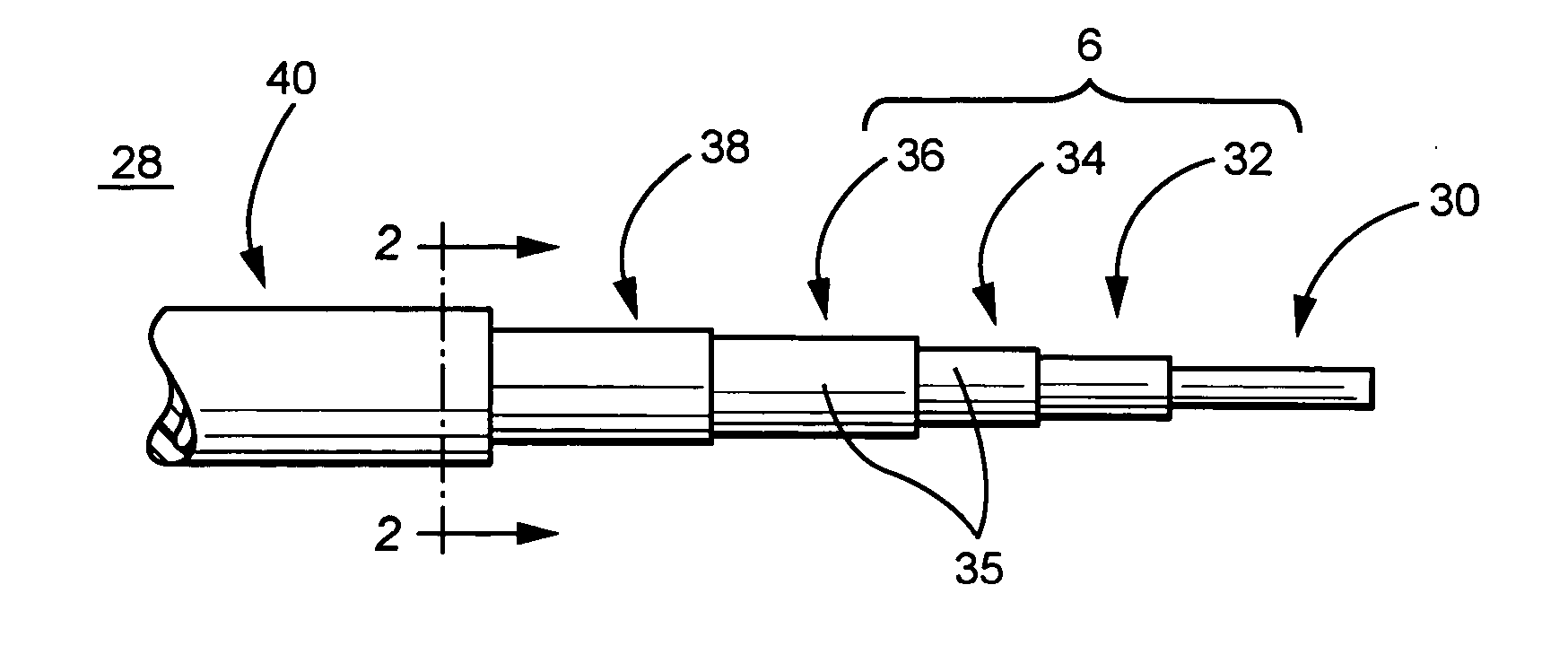
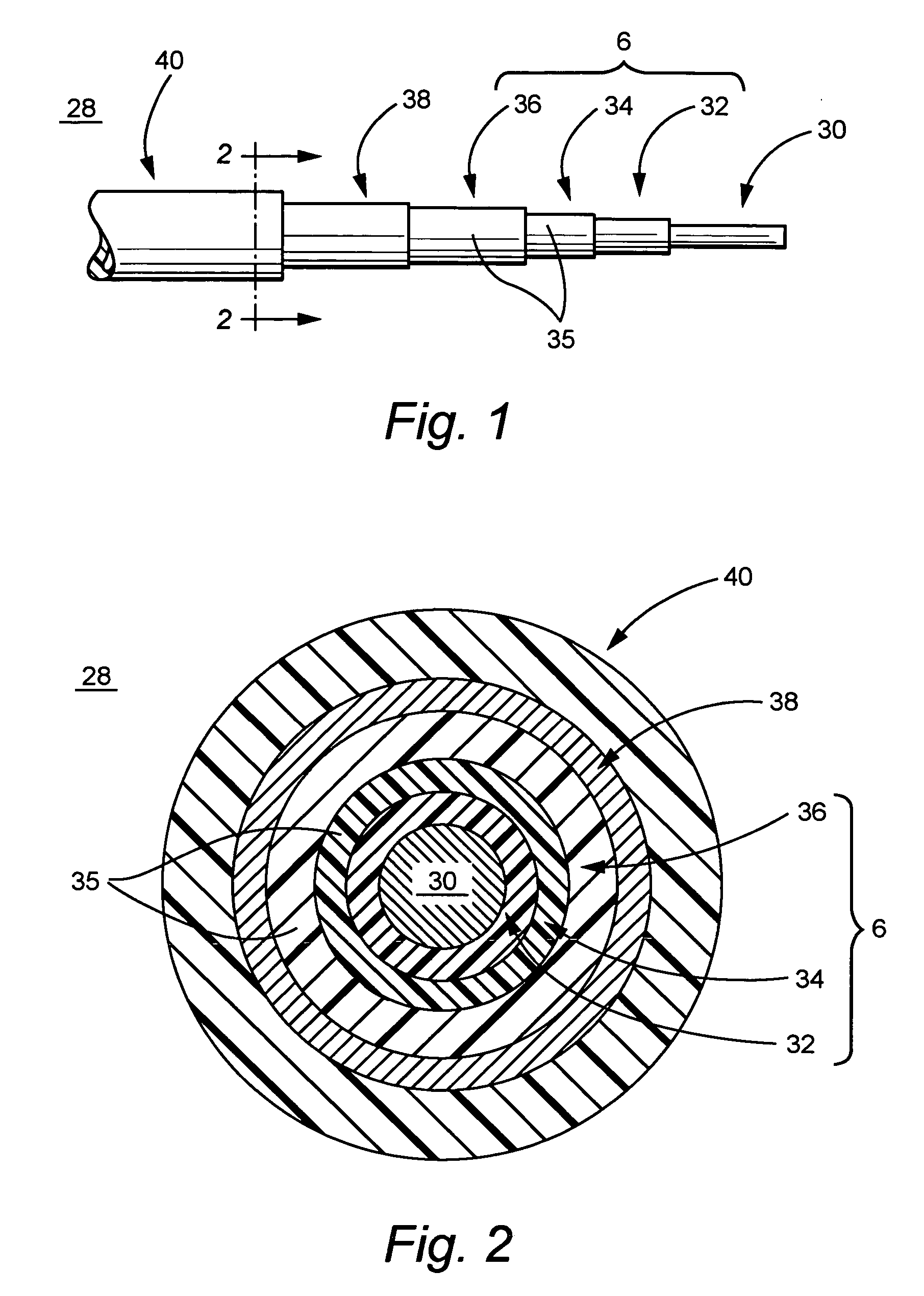
[0012]FIGS. 1 and 2 schematically illustrate a multi-axial electrically conductive cable 28 comprising an inner conductor 30, a first layer of dielectric insulating material 32, at least one second layer of dielectric insulating material 35, at least one outer conductor 38, and at least one outer insulator or “jacket”40. In one embodiment, the layers of dielectric insulating material 32, 34, 36 include at least two separable layers comprising any suitable dielectric material. In this embodiment, the multi-axial electrically conductive cable 28 comprises of a first layer 32 of insulating dielectric material and a second layer of insulating dielectric material 34.

[0013] The exemplary multi-axial cable in this embodiment comprises a coaxial cable 28 that is utilized in 75 ohm and 95 ohm electrical assembly connections in high temperature environments. The cable 28 comprises an inner conductor 28 made of seven strands of silver-covered, annealed copper steel wire. The overall diameter ...


PUM


Abstract

A multi-axial electrically conductive cable having a multi-layered core. The multi-layered core comprises one layer of insulating dielectric material and at least one additional layer of insulating dielectric material. The multiple layers of the core are separable and allow the multi-axial electrically conductive cable to be utilized in several electrical connections of varying impedances and different sized connections.

Description

BACKGROUND OF THE INVENTION [0001] This invention relates to a multi-axial electrically conductive cable with a multi-layered core that enables the cable to be utilized over a range of electrical impedance connections and diverse applications of the connections. In particular, this invention relates to a multi-axial cable with a multi-layered core and use of the cable to manufacture multi-impedance transducers for use in high temperature environments. This invention also relates to a method for manufacturing the multi-axial cable such that the cable fits in several sized electrical connections. [0002] A coaxial electrically conductive cable method of manufacture is disclosed in U.S. Pat. No. 4,508,585 to Frakes. The use of coaxial cable for the transmission of high frequency electrical signals and like applications is well known in the art. Typically, a multi-axial electrically conductive cable, specifically coaxial cable, comprises an inner conductor encased in an annular layer of ...

Claims


Application Information

Patent Timeline
IPC IPC(8): H01B7/00
CPCH01B11/1834H01R2103/00H01R43/28H01R24/562
Inventor VAN DEN BERG, DAVID CHARLESROSE, ROBERT IVAN JR.
Owner GENERAL ELECTRIC CO
Why Eureka
Try Eureka