Multi-tube separation membrane module

a technology of separation membrane and tube, applied in the direction of filtration separation, separation process, moving filter element filter, etc., can solve the problems of ineffective processing capabilities of tubular separation membrane elements b>3/b>, and the capacity of multiple tube type separation membrane modules is far less

Inactive Publication Date: 2006-01-19
BUSSAN NANOTECH RES INST
View PDF5 Cites 26 Cited by
  • Summary
  • Abstract
  • Description
  • Claims
  • Application Information

AI Technical Summary

Benefits of technology

[0007] Accordingly, an object of the present invention is to provide a multiple tube type separation membrane module which enables full use of the processing capacity of individual tubular separation membrane element in the module.

Problems solved by technology

However, the processing capabilities of the tubular separation membrane elements 3 are not fully effective, and the processing capacity of the multiple tube type separation membrane module is far less than what calculated as the sum of the processing capacity of the individual membrane elements 3.

Method used


Image

  • Multi-tube separation membrane module
  • Multi-tube separation membrane module
  • Multi-tube separation membrane module

Examples


example 1

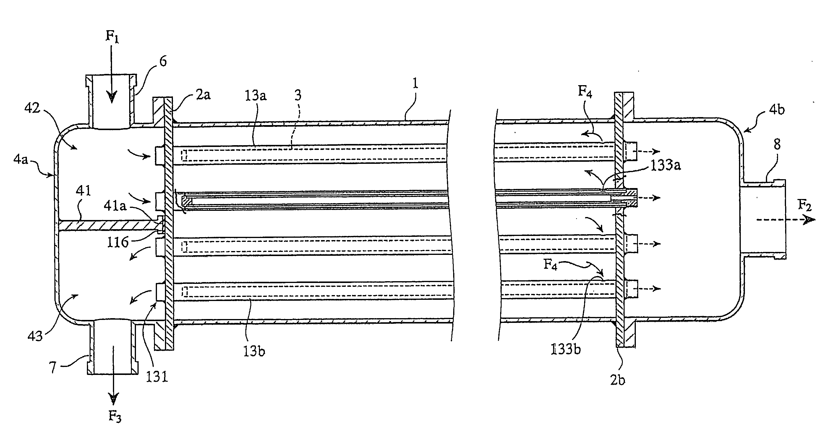
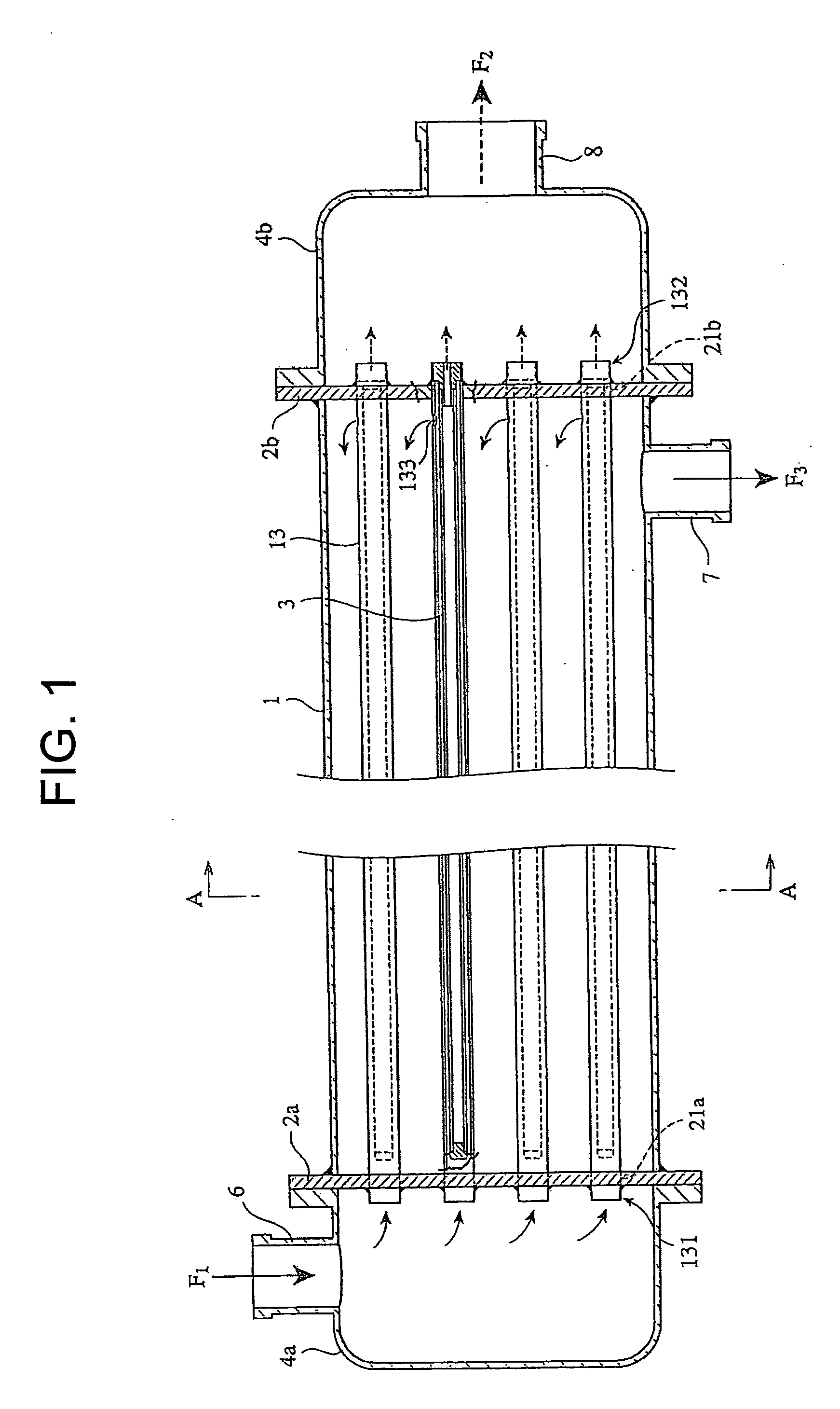
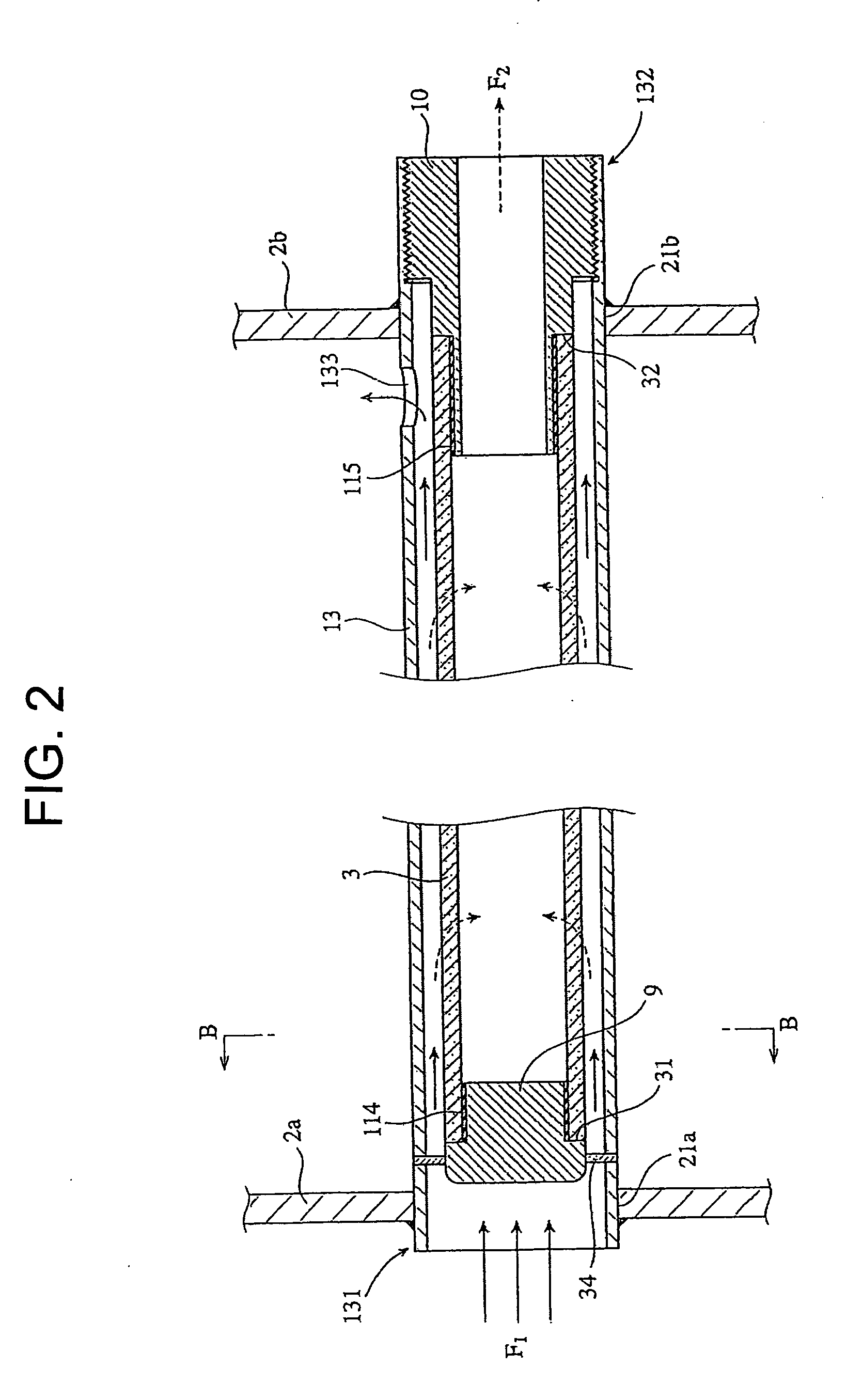
[0038] Tubular separation membrane elements 3 were made by forming zeolite membranes around tubular porous support members composed of α-alumina (length: 80 cm, outside diameter: 10 mm, inside diameter: 9 mm) , and a multiple tube type separation membrane module (length: 110 cm, outside diameter: 14 cm) similar to the embodiment shown in FIGS. 1 and 4 was assembled using 25 pieces of the tubular separation membrane elements. Mixed vapor composed of water and ethanol (water:ethanol=0.05:0.95 (mass fraction)) was supplied to a cylindrical shell 1 of the multiple tube type separation membrane module. The mixed stream was supplied at a rate of 100 kg / h, the temperature of the mixed steam was 110° C. at a fluid inlet 6 and the pressure thereof was 300 kPa. When the mixed vapor was supplied and membrane-permeable fluid outlet 8 was sacked at 1.3 kPa, membrane-permeable fluid F2 flowed out from the membrane-permeable fluid outlet 8, and non-permeable fluid F3 flowed out from fluid outlet 7...


PUM

PropertyMeasurementUnit
flow velocityaaaaaaaaaa
diameteraaaaaaaaaa

Abstract

A multiple tube type separation membrane module characterized in that said module comprises plurality of tubular separation membrane elements 3 having sealed ends and open ends; outside pipes 13 surrounding the tubular separation membrane elements 3 with spaces formed therebetween and having first openings on the sealed ends side of the tubular separation membrane elements 3 as well as second openings 133 in the vicinities of the open ends of the tubular separation membrane elements; means for inlet communicating with the first openings of the outside pipes; first means for outlet communicating with the open ends of the tubular separation membrane elements; and second means for outlet communicating with the second openings of the outside pipes, wherein fluid F1 flowing from the first openings of the outside pipes through the means for inlet flows in the spaces between the tubular separation membrane elements 3 and the outside pipes 13, component F2 separated from the fluid F1 by the tubular separation membrane elements 3 flows out from the first means for outlet through the open ends of the tubular separation membrane elements 3, and the remaining fluid F3 flows out from the second means for outlet.

Description

BACKGROUND OF THE INVENTION [0001] 1. Field of the Invention [0002] The present invention relates to a multiple tube type separation membrane module used to separate specific components from a fluid such as a solution, a mixed gas, and the like. [0003] 2. Description of the Related Art [0004] Multiple tube type separation membrane modules as equipment for separating components in solutions or mixed gases are known. The separation membrane element used in the multiple tube type separation membrane module is made by composing a membrane of zeolite and the like having fine pores approximately as large as the molecules of substances to be separated around a porous tube. [0005]FIG. 6 shows an example of a conventional multiple tube type separation membrane module. The multiple tube type separation membrane module has a cylindrical shell 1, plurality of tubular separation membrane elements 3 extending in the cylindrical shell 1, support plates 2a and 2b having plurality of opening for sup...

Claims


Application Information

Patent Timeline
Patent Type & Authority Applications(United States)
IPC IPC(8): B01D63/06B01D53/22B01D71/02
CPCB01D53/22B01D63/06B01D2321/2008B01D65/08B01D71/028B01D63/065B01D71/0281
Inventor IKEDA, SHIROSATO, RYOKI
Owner BUSSAN NANOTECH RES INST
Why Eureka
Try Eureka