
Viscous fluid metering device

a viscous fluid and metering device technology, applied in liquid/fluent solid measurement, volume measurement, open container, etc., can solve the problems of hot applied sealant mix solids coming out of suspension, and the replacement of a nozzle can significantly affect machine utilization

Inactive Publication Date: 2006-01-19
ERDMAN AUTOMATION CORP
View PDF15 Cites 1 Cited by
  • Summary
  • Abstract
  • Description
  • Claims
  • Application Information

AI Technical Summary

Benefits of technology

"The patent text describes a metering device for dispensing viscous fluids, such as sealants, that can perform consistently over an extended period of time. The device includes a gear metering device and a nozzle assembly that can be quickly assembled and disassembled. The nozzle assembly includes a nozzle holder and a resilient sealing member to provide a fluid-tight seal between the nozzle holder and the body of the nozzle. The invention also addresses the problem of solids coming out of suspension in the hot applied sealants and the need for high-temperature exposure to prevent wear and failure of mechanical components. The invention provides a solution to these problems by providing a durable metering device with a quickly connectable nozzle assembly that can be easily inspected and maintained."

Problems solved by technology

The ease of replacement of a nozzle can significantly affect machine utilization.
A further problem encountered with hot applied sealants is when they are subjected to high pressures, solids in the hot applied sealant mix will tend to come out of suspension.
For example, if a hot applied sealant material can only be subjected to a maximum pressure of 2,500 psi and there is a pressure loss passing through the passageways of the system of 1,000 psi, this can create a major problem in maintaining high enough levels of pressure in the lowest pressure areas of the system while keeping high pressure areas below the critical pressure.

Method used


Image

  • Viscous fluid metering device
  • Viscous fluid metering device
  • Viscous fluid metering device

Examples


Embodiment Construction

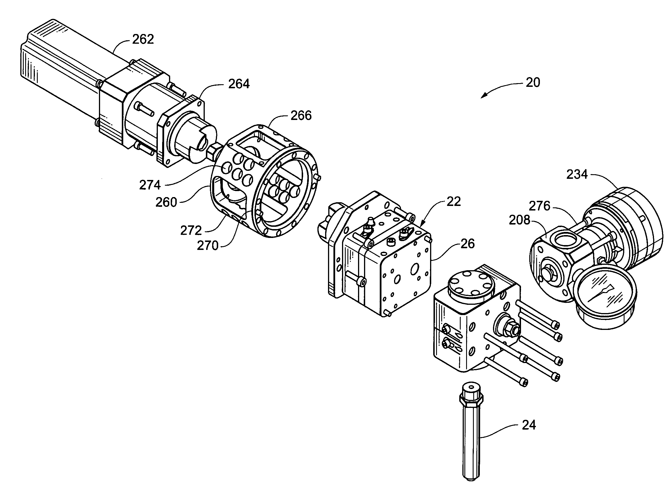
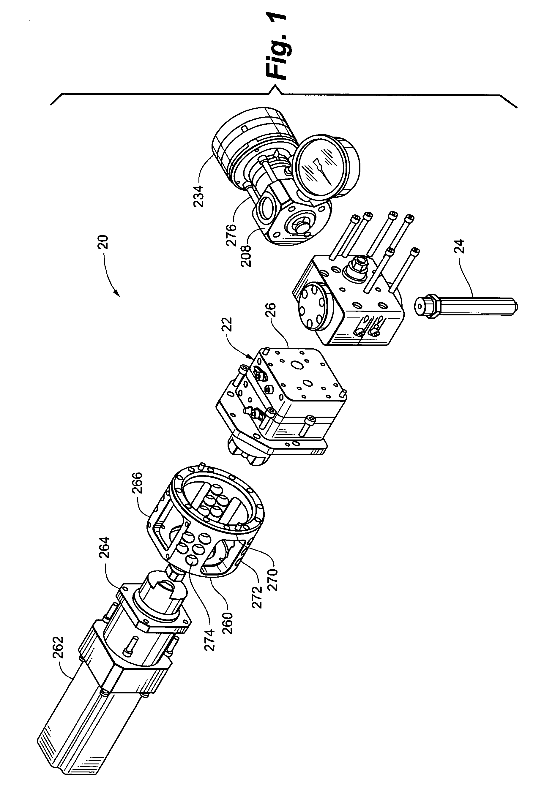
[0053] Referring to FIGS. 1, viscous liquid dispenser 20 generally includes a metering device 22 and a nozzle assembly 24. Metering device 22 is in fluid communication with nozzle assembly 24 so that viscous liquid material that leaves metering device 22 flows to and, ultimately through nozzle assembly 24. The metering device 22 generally includes metering device body 26 and gear assembly 28. Gear assembly 28 is enclosed within and surrounded by metering device body 26.

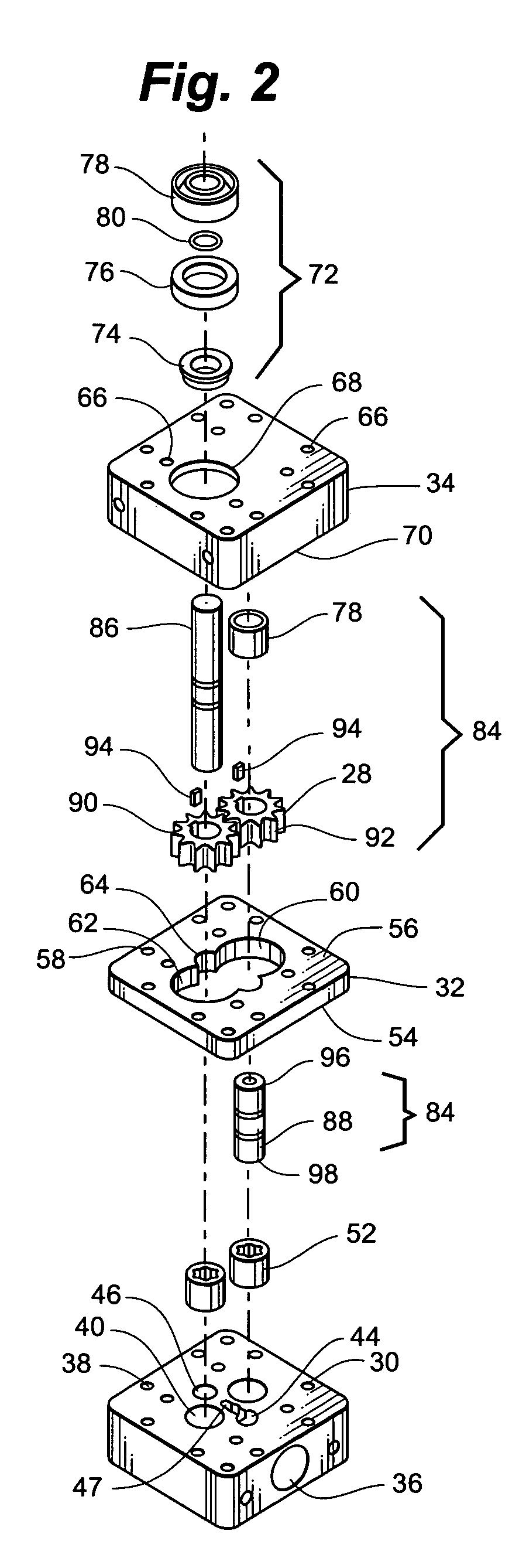
[0054] Referring to FIGS. 2, 20 and 21, metering device body 26 is generally divided into three major subcomponents, port plate 30, center plate 32 and drive plate 34. Each of port plate 30, center plate 32 and drive plate 34 have a plurality of passageways, apertures and cavities machined or otherwise formed in them.

[0055] Port plate 30 defines inlet 36, a plurality of boltholes 38 and bearing cavities 40. Inlet 36 leads to inlet passage 42 which terminates at interior inlet 44. Thus, inlet passage 42 provides for ...


PUM


Abstract

A metering device having two gears and a center plate defining a gear chamber having two major lobes to receive the gears, each of the major lobes defining a diameter and a circular segment having a perimeter extending greater than one hundred eighty degrees. The face surfaces of the first gear, the second gear and the center plate are each machined to be as precisely flat as practical and to be as precisely of equal thickness as practical. The first gear and the second gear are trued on an arbor to eliminate as much runout as practical while at the same time reducing a diameter of the first gear and the second gear to be the substantially the same or slightly larger than the diameter of the major lobes. The first gear and the second gear are press fit into the major lobes; and lapped in the major lobes.

Description

CLAIM TO PRIORITY [0001] This application is a continuation of U.S. patent application Ser. No. 10 / 794,175 which claims priority to U.S. Provisional Applications Ser. Nos. 60 / 452,606 entitled “Quick Change Nozzle” filed Mar. 6, 2003 and 60 / 454,275 entitled “Gear Pump Case” filed Mar. 13, 2003, the entire contents of the foregoing are incorporated herein by this reference. RELATED APPLICATIONS [0002] This application is related to U.S. Provisional Application Ser. No. 60 / 452,209 filed Mar. 5, 2003 entitled “System and Process for Glazing Glass to Windows and Door Frames” and to Utility Application filed on Mar. 5, 2004, with the same title, having Attorney Doc. No. 1843.02-US-02, the entire contents of which are incorporated herein by this reference.FIELD OF THE INVENTION [0003] This invention relates to dispensing viscous fluids prone to hardening, such as sealants, and more particularly relates to a metering device and nozzle for dispensing viscous fluids. BACKGROUND OF THE INVENTI...

Claims


Application Information

Patent Timeline
Patent Type & Authority Applications(United States)
IPC IPC(8): G01F11/00B67B7/00G01F11/44
CPCG01F11/44
Inventor ERDMAN, RODNEY V.BERNS, ERIC J.
Owner ERDMAN AUTOMATION CORP
Learn More