Self biased differential amplifier

Inactive Publication Date: 2006-01-19
SAMSUNG ELECTRONICS CO LTD
View PDF15 Cites 8 Cited by
  • Summary
  • Abstract
  • Description
  • Claims
  • Application Information

AI Technical Summary

Benefits of technology

[0029] According to above exemplary embodiment of the present invention, constant self-bias current is achieved without the need for usi

Problems solved by technology

Thus, the differential amplifier illustrated in FIG. 1 consumes additional current because of the additional circuits.
In addition, the limitation of output swings and imbalance between the voltages at two output terminals OUT and OUTB, reduce noise margin in the circuit.
However, the above-

Method used


Image

  • Self biased differential amplifier
  • Self biased differential amplifier
  • Self biased differential amplifier

Examples


Example

[0042] Detailed illustrative embodiments of the present invention are disclosed herein. However, specific structural and functional details disclosed herein are merely representative for purposes of describing exemplary embodiments of the present invention. This invention may be embodied in many alternate forms and should not be construed as limited to the embodiments set forth herein.

[0043] Accordingly, while the invention is susceptible to various modifications and alternative forms, specific embodiments thereof are shown by way of example in the drawings and will herein be described in detail. It should be understood, however, that there is no intent to limit the invention to the particular forms disclosed, but on the contrary, the present invention covers all modifications, equivalents, and alternatives falling within the spirit and scope of the invention. Like numbers refer to like elements throughout the description of the figures.

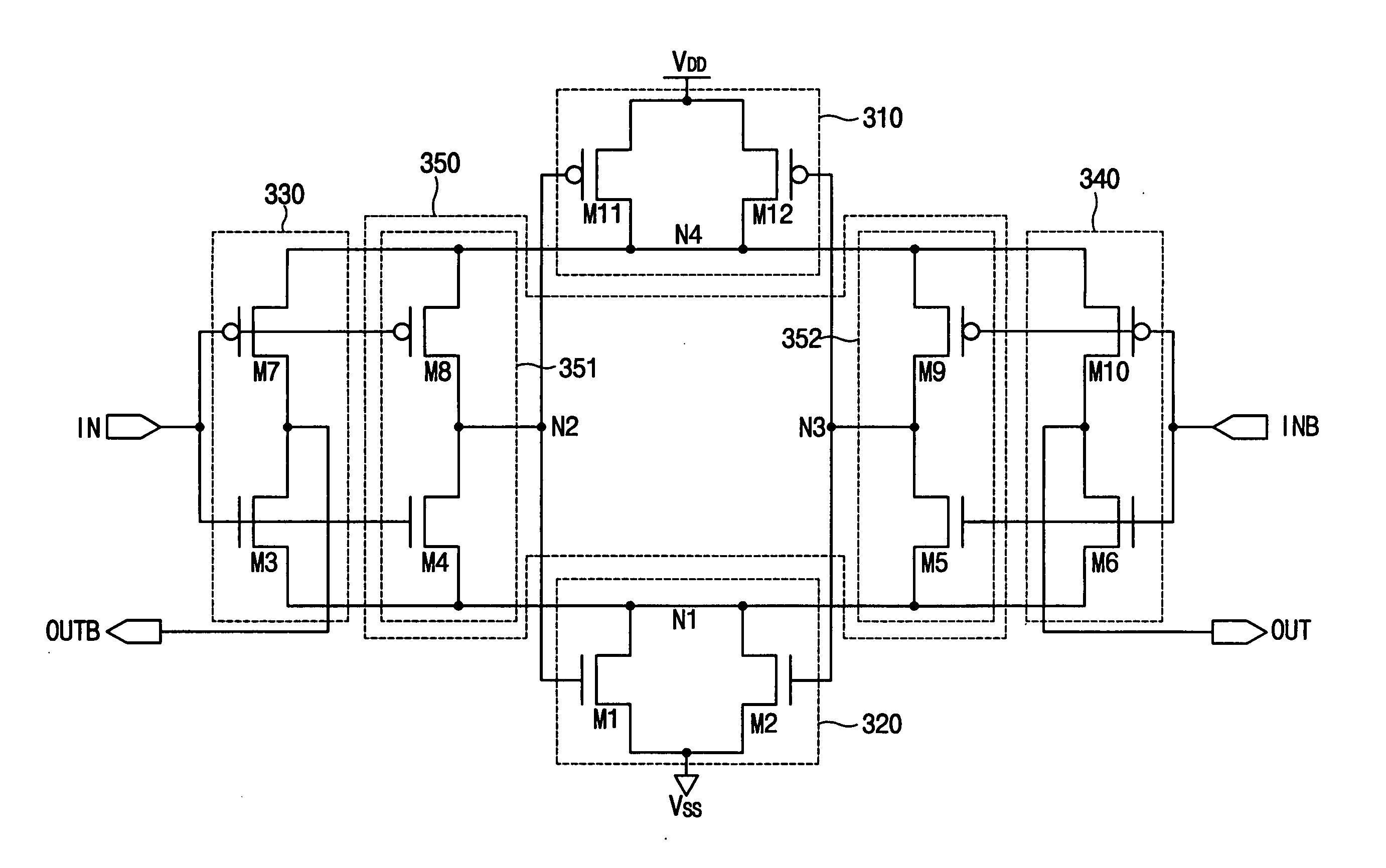
[0044]FIG. 3 is a circuit diagram illustrati...


PUM


Abstract

A differential amplifier has an upper/lower and a left/right symmetric structure. The differential amplifier improves output voltage swings and gain without the need for additional circuits for driving current sources or voltage sources. The differential amplifier includes a first current source, a second current source, a first inverter, a second inverter and a self bias control circuit. The first current source and the second current source provide a first bias current and a second bias current. The self bias control circuit maintains the first bias current and the second bias current at a constant level. Therefore, the differential amplifier provides constant current without additional circuits for driving current sources or voltage sources, and achieves a wider range of voltage output swings and a higher gain, as compared to conventional differential amplifier configurations.

Description

RELATED APPLICATIONS [0001] This application claims priority to Korean Patent Application No. 2004-53310, filed Jul. 9, 2004 in the Korean Intellectual Property Office (KIPO), the entire contents of which are incorporated herein by reference. BACKGROUND OF THE INVENTION [0002] 1. Field of the Invention [0003] The present invention relates in general to a differential amplifier, and more specifically, to a self-biased differential amplifier. [0004] 2. Description of the Related Art [0005] A differential amplifier is a circuit that is commonly employed for amplifying an input signal. Such amplifiers enjoy widespread use in many applications, for example as an input buffer or a receiver. The differential amplifier is commonly used as a receiving stage for a signal channel used for transferring signals between integrated circuits, or chips. [0006] The differential amplifier receives first and second input signals via two complementary input terminals to generate output signals at two co...

Claims


Application Information

Patent Timeline
IPC IPC(8): H03F3/45
CPCH03F3/45188H03F2203/45454H03F2203/45371H03F3/45
Inventor KIM, JI-HYUN
Owner SAMSUNG ELECTRONICS CO LTD
Why Eureka
Try Eureka