
Lithographic apparatus and device manufacturing method

a technology of lithographic apparatus and manufacturing method, which is applied in the direction of printers, instruments, photographic processes, etc., can solve the problems of difficult to predict in advance how well a given metrology target will perform, and achieve the effects of preventing excessive mechanical and/or chemical attack, and reducing the quality of a given metrology targ

Active Publication Date: 2006-01-19
ASML NETHERLANDS BV
View PDF37 Cites 11 Cited by
  • Summary
  • Abstract
  • Description
  • Claims
  • Application Information

AI Technical Summary

Benefits of technology

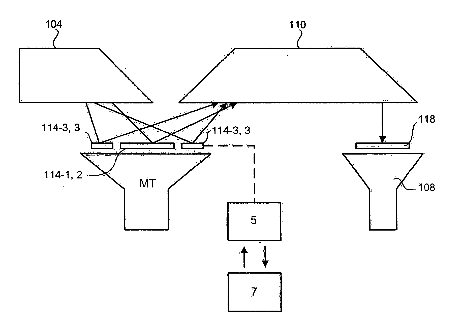
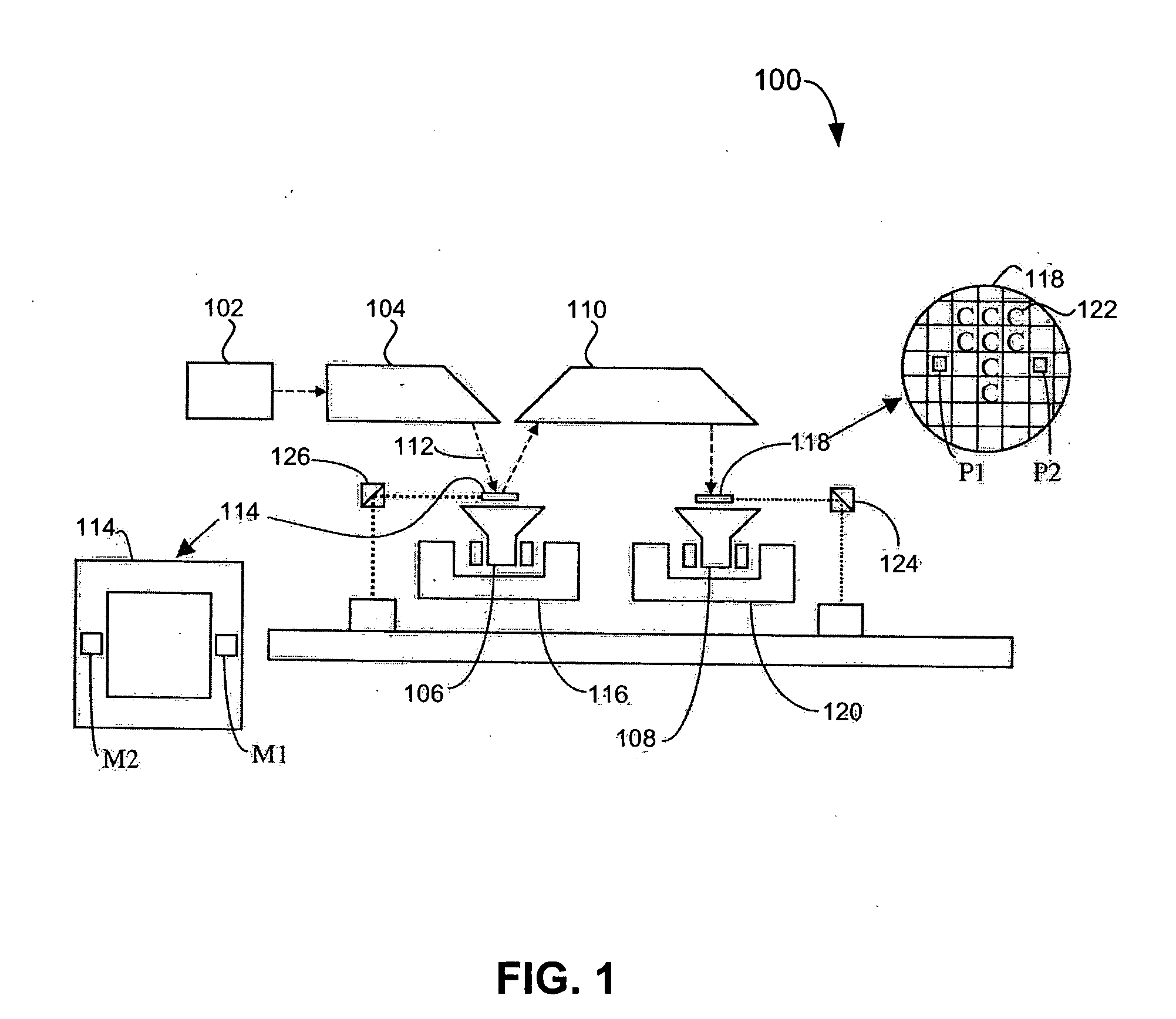
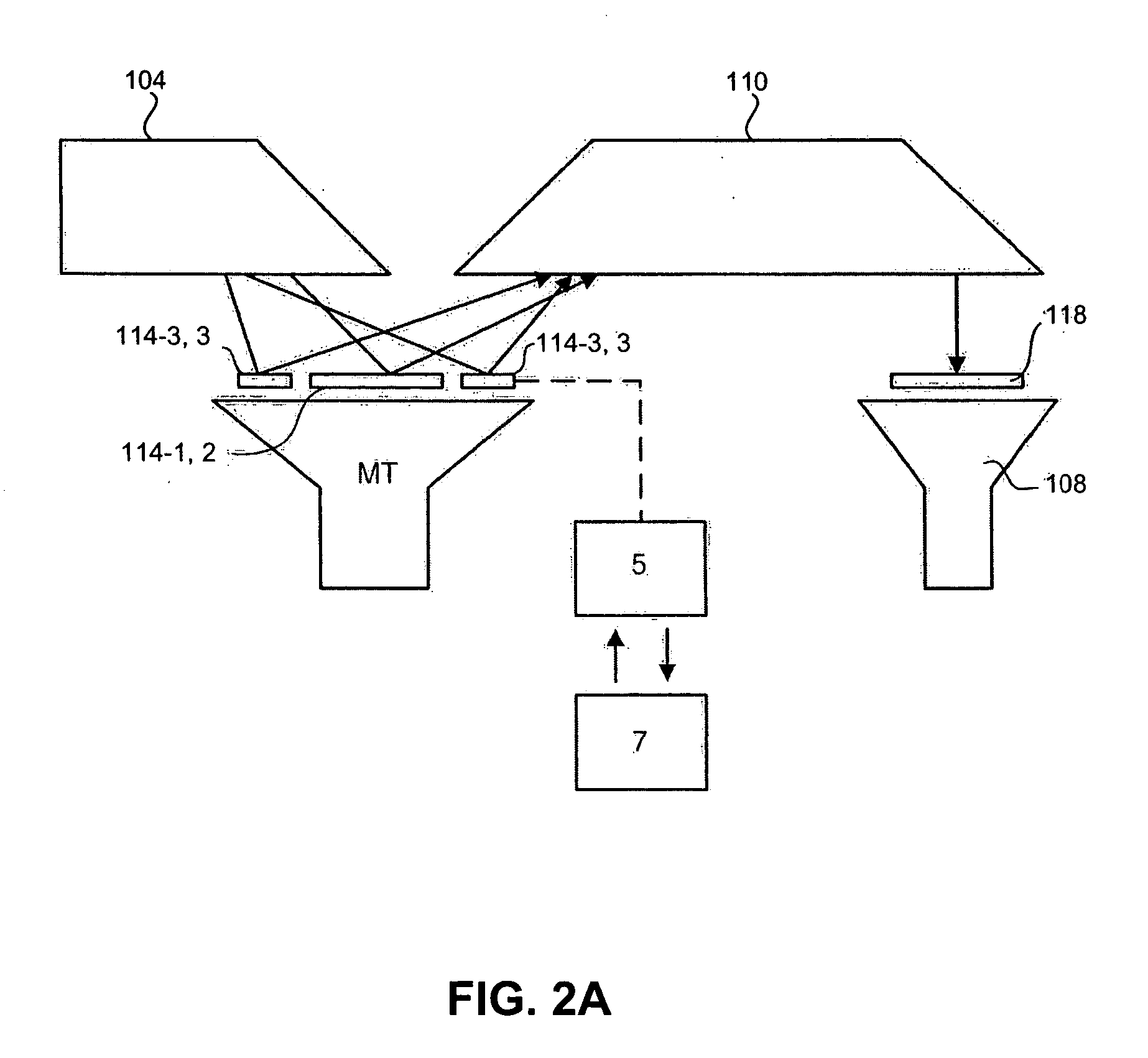
The present invention provides a lithographic apparatus with a separate metrology target patterning device and a metrology target inspection device. The metrology target patterning device can adjust its pattern independently of the product pattern, allowing for easy optimization of the metrology target without changing the product pattern. The apparatus also includes an illumination system, a substrate table, and a metrology target patterning device controller that can adjust the metrology target pattern based on information from inspection of a previously imaged substrate. The metrology target patterning device can also include a plurality of metrology targets for testing and optimizing purposes. The technical effects of this invention include improved accuracy, flexibility, and efficiency in optimizing the metrology target pattern.

Problems solved by technology

It is often difficult to predict in advance how well a given metrology target (and in particular the substructure associated with a metrology target) will perform.

Method used


Image

  • Lithographic apparatus and device manufacturing method
  • Lithographic apparatus and device manufacturing method
  • Lithographic apparatus and device manufacturing method

Examples


Embodiment Construction

Overview and Terminology

[0048] Although specific reference may be made in this text to the use of lithographic apparatus in the manufacture of integrated circuits (ICs), it should be understood that the lithographic apparatus described herein may have other applications, such as the manufacture of integrated optical systems, guidance and detection patterns for magnetic domain memories, flat panel displays, thin-film magnetic heads, etc. The skilled artisan will appreciate that, in the context of such alternative applications, any use of the terms “wafer” or “die” herein may be considered as synonymous with the more general terms “substrate” or “target portion,” respectively. The substrate referred to herein may be processed, before or after exposure, in for example a track (e.g., a tool that typically applies a layer of resist to a substrate and develops the exposed resist) or a metrology or inspection tool. Where applicable, the disclosure herein maybe applied to such and other s...


PUM


Abstract

A lithographic apparatus and method comprise an illumination system arranged to provide a radiation beam, a support structure configured to support a product patterning device and a metrology target patterning device. The product patterning device imparts a radiation beam derived from the illumination system with a product pattern in its cross-section representing features of a product device to be formed. The metrology target patterning device imparts the radiation beam with a metrology target pattern in its cross-section representing at least one metrology target. The product patterning device is separate from the metrology target patterning device. A substrate table holds a substrate. A projection system project the radiation patterned by the product patterning device and the metrology target patterning device onto a target portion of the substrate. A metrology target patterning device controller adjusts the metrology target pattern independently of the product pattern.

Description

BACKGROUND OF THE INVENTION [0001] 1. Field of the Invention [0002] The present invention relates to a lithographic apparatus and a device manufacturing method. [0003] 2. Related Art [0004] A lithographic apparatus is a machine that applies a desired pattern onto a target portion of a substrate. The lithographic apparatus can be used, for example, in the manufacture of integrated circuits (ICs), flat panel displays, and other devices involving fine structures. In a conventional lithographic apparatus, a patterning means, which is alternatively referred to as a mask or a reticle, may be used to generate a circuit pattern corresponding to an individual layer of the IC (or other device), and this pattern can be imaged onto a target portion (e.g., comprising part of one or several dies) on a substrate (e.g., a silicon wafer or glass plate) that has a layer of radiation-sensitive material (e.g., resist). Instead of a mask, the patterning means may comprise an array of individually contro...

Claims


Application Information

Patent Timeline
Patent Type & Authority Applications(United States)
IPC IPC(8): G03B27/42
CPCG03F7/70283G03F7/70733G03F7/70683
Inventor HINNEN, PAUL CHRISTIAANFRANCISCUS VAN HAREN, RICHARD JOHANNESGERTRUDUS SIMONS, HUBERTUS JOHANNES
Owner ASML NETHERLANDS BV
Learn More