Device and method for determining the level of an input signal intended to be applied to a receiving system

a technology for determining the level of an input signal and a receiving system, which is applied in the direction of electrical equipment, radio transmission, transmission, etc., can solve the problems of increasing the cost price and the size of the device, and reducing the service life of the devi

Inactive Publication Date: 2006-01-19
NXP BV
View PDF7 Cites 17 Cited by
  • Summary
  • Abstract
  • Description
  • Claims
  • Application Information

AI Technical Summary

Benefits of technology

[0020] This additional characteristic allows decreasing the noise contained in the output signal, which permits to precisely determine the level of the input signal.
[0022] This additional characteristic permits to statistically enhance the precision of the level of the input signal and thus to reduce the measuring error.
[0024] The look-up table permits to know the real gain of each amplifier, which permits to precisely derive the level of the input signal.
[0027] This additional characteristic allows generating a digital value of the output signal level which is expressed in Decibels, which value can directly be used for determining the level of the input signal.

Problems solved by technology

These known devices have a certain number of limitations in so far as the calibration tables are to be recalculated for each component, which renders the manufacture of such devices costly, considering the time necessary for the calibration.
On the other hand, these tables store many data, which implies that an additional memory of the EPROM type is used, which increases the cost price and the size of the device.
Finally, at the end of the manufacturing process, these devices are often not compliant with the DOCSIS V1.1 standard because they do not respect the precision of the input signal that is determined.
A costly selection from all these devices is thus to be made to select only the compliant devices.

Method used


Image

  • Device and method for determining the level of an input signal intended to be applied to a receiving system
  • Device and method for determining the level of an input signal intended to be applied to a receiving system
  • Device and method for determining the level of an input signal intended to be applied to a receiving system

Examples


Embodiment Construction

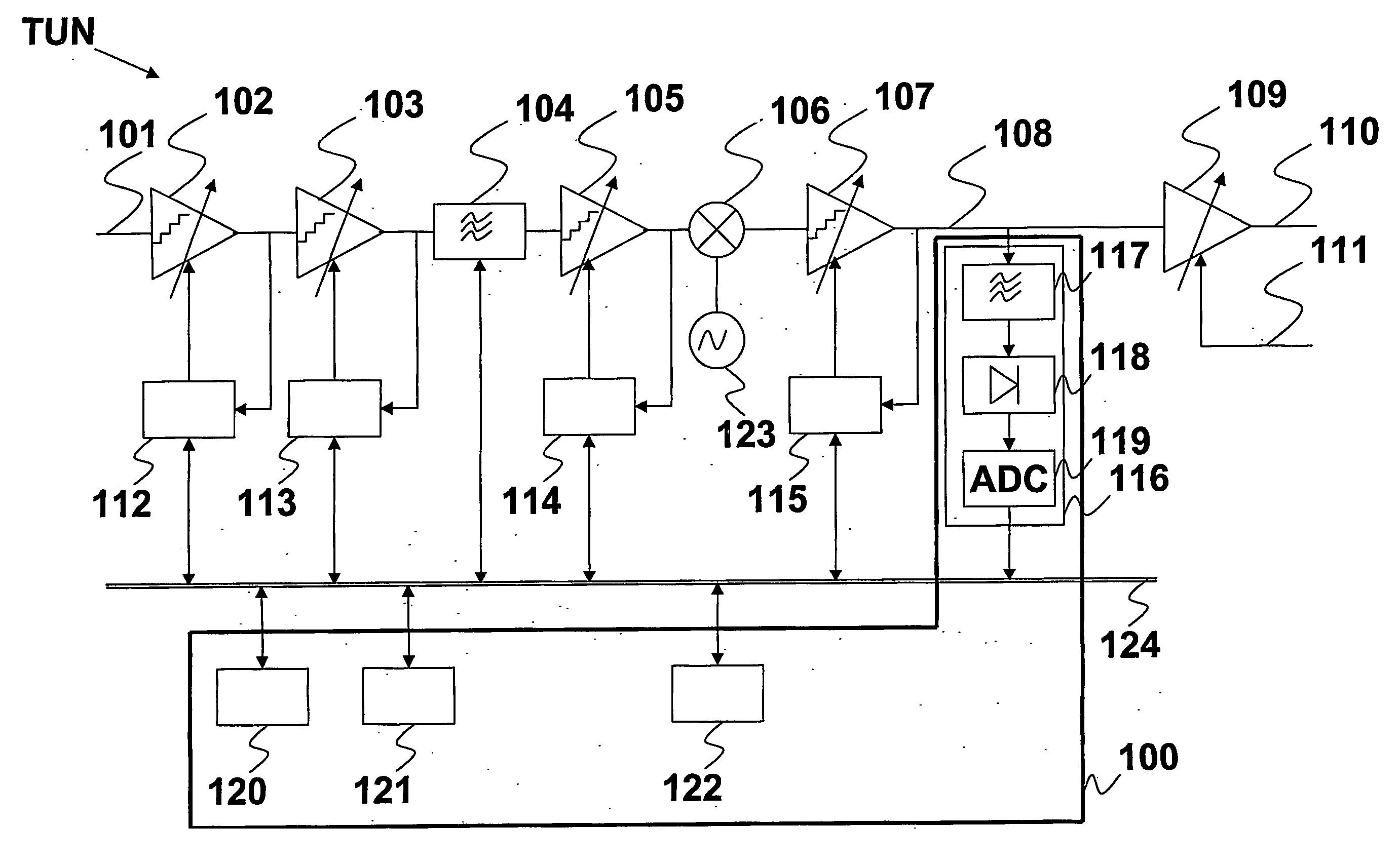
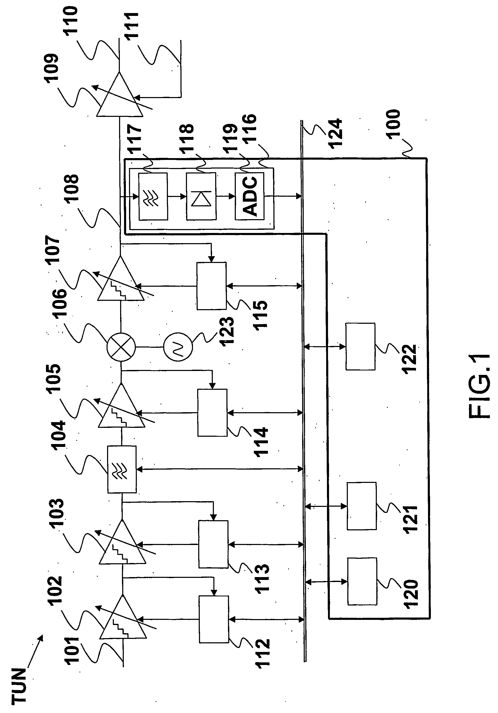
[0036]FIG. 1 describes a receiving system comprising a tuner TUN, and a device 100 according to the invention. The receiving system receives on its input a radio-frequency (RF) signal 101 whose level for a given frequency channel is determined by the device 100 according to the invention. The receiving system comprises arranged in series: [0037] an amplifier 102 receiving the input signal 101, whose nominal gain is defined by a control device 112 via the sending of a digital control word, [0038] an amplifier 103 whose nominal gain is defined by a control device 113 via the sending of a digital control word, [0039] a selective filter 104 intended to suppress high-order harmonics in the input signal 101, [0040] an amplifier 105 whose nominal gain is defined by a control device 114 via the sending of a digital control word, [0041] a mixer 106 for performing a frequency change in the amplified input signal 101 via a multiplication of a periodic signal coming from an oscillator 123, [004...


PUM


Abstract

The invention relates to a device for determining the level of an input signal (101) intended to be applied to a receiving system (TUN), said receiving system (TUN) comprising arranged in series a set of discrete gain amplifiers (102-103-105-107), a selective filter (104), a mixer (106), said receiving system (TUN) being intended to deliver an output signal (108), said device comprising: measuring means (116) for measuring the level of said output signal (108) in a given frequency channel, means (120) for determining the real gain (G1) of said set of amplifiers (102-103-105-107) in said given frequency channel, means (121) for determining the real gain (G2) of said selective filter (104) in said given frequency channel, calculation means (122) for deriving the level of the input signal (101) from the level of the output signal (108), the real gain (G1) of said set of amplifiers (102-103-105-107) and from the real gain (G2) of said selective filter (104).

Description

FIELD OF THE INVENTION [0001] The invention relates to a device for determining the level of an input signal intended to be applied to a receiving system, said receiving system comprising arranged in series a set of discrete gain amplifiers, a selective filter, a mixer, said receiving system being intended to deliver an output signal. [0002] The invention has numerous applications in appliances intended to receive a radio-frequency signal (RF) whose level is to be determined. BACKGROUND OF THE INVENTION [0003] The development of cable networks implies to establish a fast diagnosis of installations of which the service providers are in charge and in control. [0004] In order to be able to rapidly verify the cable system at the level of each user, that is to say, at the level of the receiving systems, the receiving systems (for example a so-called set top box or cable modem comprising a tuner) are to have the RSSI functionality (Received Signal Strength Indicator) in conformity with Am...

Claims


Application Information

Patent Timeline
Patent Type & Authority Applications(United States)
IPC IPC(8): H04B1/06H04B7/00H03G3/00H03G3/30
CPCH03G3/3068H03G3/001H03G3/30H04B1/18H03G3/00
Inventor SENESCHAL, FRANCOISMAUPAS, ALEXANDRE
Owner NXP BV
Why Eureka
Try Eureka