Resectoscope comprisig positioned optics

Inactive Publication Date: 2006-01-19
OLYMPUS WINTER & IBE
View PDF5 Cites 8 Cited by
  • Summary
  • Abstract
  • Description
  • Claims
  • Application Information

AI Technical Summary

Benefits of technology

[0018] In accordance with the invention, the optical system is supported in the angular range of the carrier with respect to the tubular shaft with a two-point support system, whereby it is reliably positioned. The support can advantageously be effected such that the optical system is pressed against the tubular shaft at a third, opposite position so that it is situated in a precise three-point positioning system. The support device imparts lateral guidance to the carrier in order to prevent variations in the circumferential angular direction. For its radial positioning, the carrier can be guided in the conventional manner, for instance as illustrated in FIG. 1, with the sliding tube 10 on the optical system 2. The guide tube 11 is omitted in the construction in accordance with the invention with its cleaning problems. The entire optical guide tube can also be saved. The possibility is also produced by comparison with the prior art, as is illustrated in FIG. 1, of arranging the entire positioning device of the optical system and the carrier closer to the distal end of the tubular shaft and thus with a better positioning action on the instrument itself.
[0020] The webs can be constructed in the interior of the tubular shaft on the latter, e.g. by soldering or by the formation of indentations on the tubular shaft. A very simple and precisely positioning construction is thus produced.
[0025] The non-circular peripheral profile of the tubular shaft results in a precise angular positioning of the support device sliding in profiled engagement with the tubular shaft and thus in a better circumferential angular guidance of the carrier.

Problems solved by technology

This known construction has disadvantages, particularly as regards the guide tube 11, which is difficult to clean as a result of its small diameter.
As a result of the optical guide tube 4, the overall construction of the resectoscope is made more expensive and cleaning problems are produced as regards also the narrow guide tube 11.

Method used


Image

  • Resectoscope comprisig positioned optics
  • Resectoscope comprisig positioned optics
  • Resectoscope comprisig positioned optics

Examples


Embodiment Construction

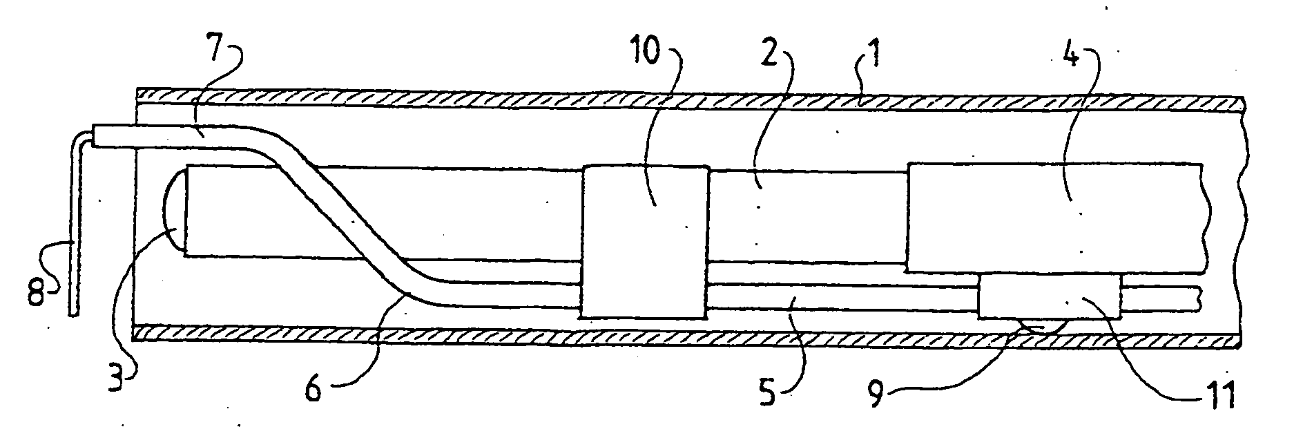
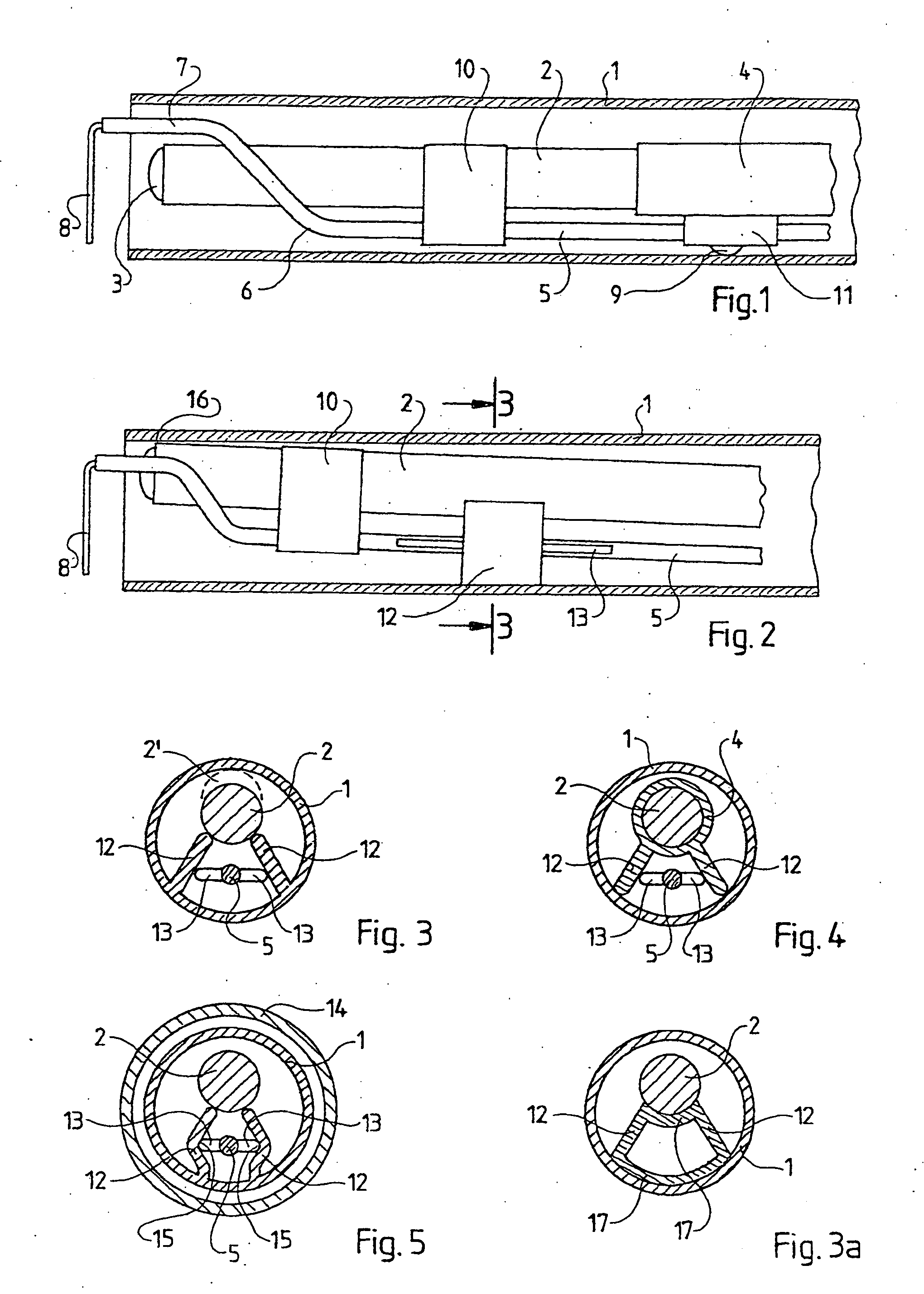
[0032]FIGS. 2 and 3 show a first embodiment of the invention corresponding to the extent possible with FIG. 1 and using, to the extent possible, the same reference numerals. The tubular shaft 1 or the inner shaft of a multi-tube resectoscope is again shown. The carrier 5, which substantially corresponds to that in FIG. 1, is guided in the same manner in this embodiment at a radial spacing on the optical system 2 with the sliding tube 10, as in the known construction of FIG. 1.

[0033] The construction of FIG. 2 has no optical guide tube. The support of the optical system 2 with respect to the tubular shaft 1 is effected by means of two webs 12, as is shown in the sectional view on the line 3-3 in FIG. 3. The webs extend in the radial direction between the optical system 2 and the tubular shaft 1 and are constructed integrally with the tubular shaft 1 in the exemplary embodiment of FIGS. 2 and 3. As shown in FIG. 3, a reliably positioning engagement for the optical system 2 is produce...


PUM


Abstract

A urological resectoscope is disclosed, having a tubular shaft (1), through which an optical system (2) and a longitudinally moveable instrument carrier (5) pass. The optical system (2) is supported with respect to the tubular shaft (1) at a spacing from the proximal end of the tubular shaft (1) with a support device (9, 12). The carrier (5) is positioned with a radial positioning device (10, 15) and a circumferential angular positioning device (11, 12). The support device (12, 18, 18′) is so arranged adjacent to the optical system (2) in the region in which the carrier (5) extends, that it supports the optical system (2) with respect to the tubular shaft (1) with a two point support system and imparts lateral guidance to the carrier (5) in the circumferential angular direction.

Description

BACKGROUND OF THE INVENTION [0001] 1. Field of the Invention [0002] The invention relates to a urological resectoscope of the type having a tubular shaft through which an optical system and a longitudinally moveable instrument carrier pass. [0003] 2. Description of Related Art [0004] Resectoscopes constitute the principal device in urological surgery and are used, in particular, for prostate resections. They may also be used in gynaecology. As the instrument they have a knife or generally the conventional cutting loop, to which high frequency may be applied, which may be advanced forwardly beyond the tubular shaft. The instrument is used in the region in front of the distal end of the tubular shaft whilst optically viewing through the optical system. The tubular shaft can be a simple tube or can consist of an outer shaft and an inner shaft, when the resectoscope is constructed in the form of a continuous flow resectoscope, the optical system and the elongate instrument carrier carry...

Claims


Application Information

Patent Timeline
IPC IPC(8): A61B1/00A61B18/14
CPCA61B18/149
Inventor AUE, THOMASBUAA, WERNERBROMMERSMA, PIETERNUSSBAUM, FELIX
Owner OLYMPUS WINTER & IBE
Why Eureka
Try Eureka