System, method, and apparatus for portable design, deployment, test, and optimization of a communication network

a communication network and portable technology, applied in the field of portable systems for design, deployment, test and optimization of communications systems, can solve the problems of inability to meet the needs of users,

Inactive Publication Date: 2006-01-19
RAPPAPORT THEODORE S +2
View PDF99 Cites 68 Cited by
  • Summary
  • Abstract
  • Description
  • Claims
  • Application Information

AI Technical Summary

Benefits of technology

[0015] According to the present invention, a system is provided for allowing a system designer to dynamically model a communications system electronically in any environment. The method includes the selection and placement of models of various communications system hardware components, such as hubs, routers, switches, antennas (point, omnidirectional, directional, leaky feeder, distributed etc.), transceivers, amplifiers, cables, splitters, and the like, and allows the user to visualize, in three-dimensions, the effects of their placement and movement on overall system performance throughout the modeled environment. Thus, the placement of components can be refined and fine-tuned prior to actual implementation of a system to ensure that all required regions of the desired service area are blanketed with adequate RF coverage, data throughput, or system performance. The three-dimensional visualization of system performance provides system designers with tremendous insight into the functioning of the modeled communication system, and represents a marked improvement over previous visualization techniques. Furthermore, the invention allows maintenance personnel to retrieve and inspect previous designs, or to rapidly locate components while in a particular location.
[0018] An important focus of this invention is the use of miniature, hand-held (e.g., Palm), portable computers which have been adapted to provide a technician with a display of all or a portion of a three dimensional model, allow for on-site manipulation of the model (e.g., adjustments as to choice of equipment, placement in the space, and orientation) to obtain performance prediction and other valuable information. These hand-held portable client computers also provide a measurement capability for measuring various communications performance parameters within the space which measurements can be utilized either in the hand-held, portable client computers and / or be transmitted to one or several server computers, which may or may not be similar hand-held portable computers. During testing, actual performance values may be measured and entered into the hand-held computer (or gathered directly if the hand-held computer is equipped with an appropriate measurement device) and either sent to one or more of the servers for display, logging, and tuning the prediction models or for use in the prediction models on board the hand-held computer. In addition, the hand-held portable client computers may be equipped with global positioning technology or other location equipment which allow the technician to locate himself within a building or campus. Used in conjunction with the measurement features, the technician can have the portable hand held computer sample various measurements either overtly or passively in the background and have them paired to location information which will assist in modeling the space and making various optimizing changes in the deployed system. Many other advantages in deploying, testing, and optimizing communication networks may be achieved using the hand-held portable client computers, either alone or in combination with the server computers. Preferably, the hand-held portable client computers will allow for the selection of various buildings in a campus environment and display various floor plan layouts for multi-story buildings selected by the technician.
[0019] A method for representing sophisticated 3-D vector databases of buildings and campuses of buildings is described. With this system, a field technician can carry the hand-held computer into the field and use the displayed information to select placement of the components and build the physical communication system. Another advantage of the system is that field engineers can modify the plan while building the physical system. Modifications such as removing, adding, or editing positions or parameters of components can be entered into the hand-held computer acting as a client and can be transmitted to the server where an updated environment and prediction model can be calculated and sent back to the hand-held computer. Alternatively, calculations can be performed at the hand held computer, the modifications can be made, and the updated model can then be uploaded to the server. Thus, this system allows for bi-directional data flow between the client and server. Other data, such as measured or predicted network performance parameters, files, photographs, notes, and general information may be embedded or sent separately with the model.

Problems solved by technology

Due to the increasingly diverse applications of wireless communication systems, system designs have become increasingly complicated and difficult to implement.
However, measurement acquisition within in-building environments is much more tedious and time consuming than in the macrocellular environment where measurement acquisition is carried out using Global Positioning System data to determine the location of the measurement being taken.
Global Positioning System (GPS) data, which so many RF engineers have come to rely upon for outdoor measurement acquisition, is not an option for microcell environments.
Therefore, recording real-time measurement data within a building becomes a laborious, time-consuming task involving scratched notes and blueprints and manual data entry which are both expensive and ineffectual in many respects.
While the above-mentioned design and verification tools have aided wireless system designers in creating indoor wireless communication systems using building drawings and linking data measurements to building drawings, none of the devices, except for InFielder™ and Predictor™, incorporate three-dimensional building drawings to enhance the design process.
Further, the above-mentioned devices and systems lack the ability to track a roving user while autonomously or passively measuring or collecting network performance data while uploading or downloading the data to a remote monitoring location.
These products do not address the complexities of the three dimensional world of in-building systems, which is significantly more difficult to model and visualize due to multiple stories or unique three dimensional features.
Furthermore, these products only allow viewing and retrieval, and do not permit on-site or remote adjustment and manipulation of modeled features.

Method used


Image

  • System, method, and apparatus for portable design, deployment, test, and optimization of a communication network
  • System, method, and apparatus for portable design, deployment, test, and optimization of a communication network
  • System, method, and apparatus for portable design, deployment, test, and optimization of a communication network

Examples


Embodiment Construction

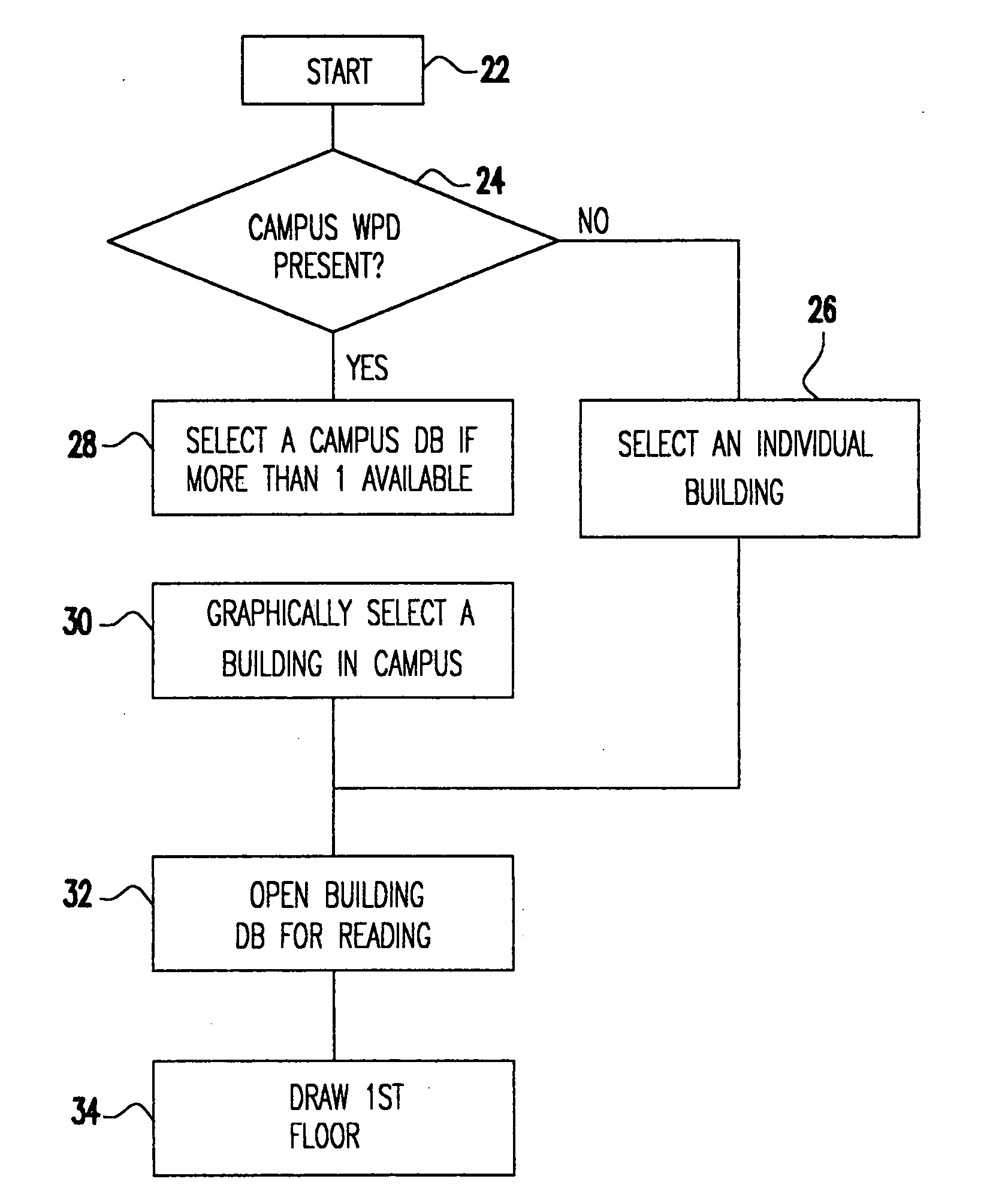
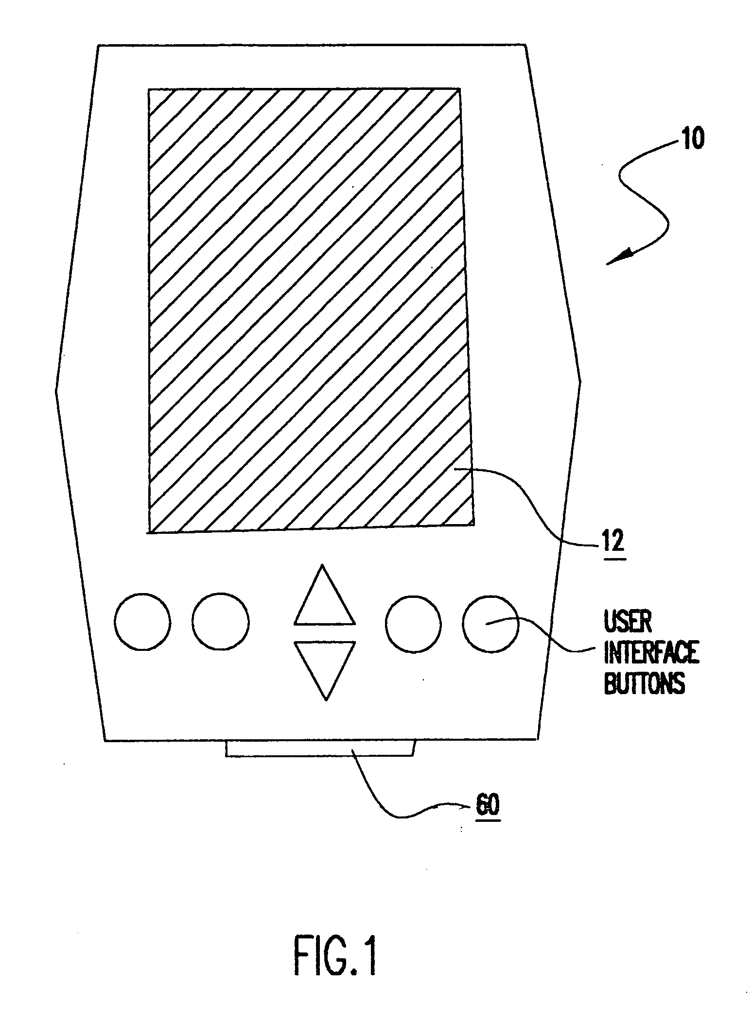
[0031] Using the present invention, it is now easier than ever to design, deploy, test, optimize, and maintain communication networks in and around multi-floored buildings, campuses of multi-floored buildings, and environments including outdoor 3-D terrain. The present method is a significant advance over the prior art in the breadth of information presented to the user while operating a portable handheld computer. Using the embodiment presented, an engineer can cover the complete cycle of design, deployment, test, and maintenance for a communications network.

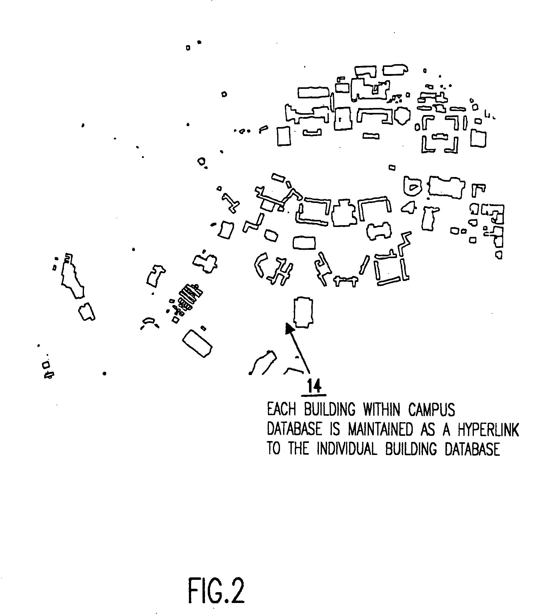
[0032] To facilitate navigation within a multi-floored building or campus of multi-floored buildings or in an outdoor 3-D environment, the present invention provides for a computer aided design (CAD) or other similar system to assist in creating graphical drawings representing the building system. Being able to smoothly navigate within a physical environment including a building or campus of buildings is critical for the afore...


PUM


Abstract

A system and method which employ one or more portable hand held computers and one or more servers, allows a field engineer to complete the entire design, deployment, test, optimization, and maintenance cycle required to implement successful communications networks. The portable hand held computer provides the user with a three-dimensional display of the physical environment in which a communications network will be deployed or optimized. The engineer may take the portable hand held computer into the field, and make alterations to the components, position of the components, orientation of the components, etc. based on on-site inspection. As these alterations to the computerized model are made, predictions for the effects these changes will have on the communications network are displayed to the engineer. Measurements may also be made using equipment connected to or contained in the portable hand held computer, and these measurements may be used to optimize performance criteria. Information can be transmitted to and from the portable hand held computer and the server to allow for complex processing to be performed using portable computer. The system allows the engineer to remain in the field while deploying the communications network, making measurements within the network, receiving optimized predictions on the performance of the network, re-configuring the communications network and associated components, and repeating the entire cycle to achieve maximum possible performance with minimal required time or effort.

Description

BACKGROUND OF THE INVENTION [0001] 1. Field of the Invention [0002] The invention generally relates to a miniature portable system for design, deployment, test, and optimization of a communications system, such as an indoor or campus-wide wireless or wired communication network. A handheld computing platform is used for the collection and display of communication signal properties, the manipulation of communication system components in a communications network design, and the prediction and optimization of communication systems during design, deployment, or maintenance operations. [0003] 2. Description of the Related Art [0004] In recent years the use of wireless communication technology, such as cellular phone networks, has greatly increased. Moreover, it has become common to implement wireless communication systems within buildings or large facilities comprising several buildings. Examples of typical wireless communication systems are local area networks (LAN), wide area networks ...

Claims


Application Information

Patent Timeline
Patent Type & Authority Applications(United States)
IPC IPC(8): G06F17/00G06Q50/00G06Q10/00H04B7/26H04L12/24H04W16/18H04W24/00
CPCH04L41/12H04L41/145H04L41/22H04W16/18H04L41/147H04W24/00Y04S40/164Y10S715/964H04W16/20Y04S40/00G06F15/173
Inventor RAPPAPORT, THEODORE S.GOLD, BRIAN T.SKIDMORE, ROGER R.
Owner RAPPAPORT THEODORE S
Why Eureka
Try Eureka