Method for providing user authentication/authorization and distributed firewall utilizing same

a distributed firewall and user authentication technology, applied in the field of network firewall systems, can solve the problems of significant barriers to the evolution of end-system communication, choke points in the middle of the network, and inability to enable communication to scal

Inactive Publication Date: 2006-01-19
MICROSOFT TECH LICENSING LLC
View PDF5 Cites 48 Cited by
  • Summary
  • Abstract
  • Description
  • Claims
  • Application Information

AI Technical Summary

Benefits of technology

[0012] The distributed firewall architecture of the present invention performs user authentication at a first level to establish a user security context for traffic from that user. Once authenticated, an authority context provides authorization for subsequent traffic from that user. This authority context may be ba...

Problems solved by technology

Unfortunately, inspection points in the middle of the network are a choke point.
That is to say, they do not enable communications to scale because they necessarily slow down end-to-end communication in order to inspect packets.
This creates significant barriers for end-system communications to evolve quickly by requiring or utilizing multi-tier application architectures that move further away from true end-to-end communication.
The multiple middle points, which are each fixed in their individual functionality, result in an overall system that results in very complex and costly management of the many independent systems.
Many of these applications did not do a good job, were shipped with insecure defaults, or could easily be made insecure by accident.
Further, data has revealed that the public network may not be the only hostile environment from which end system machines must be protected.
Indeed, it appears that network users within the private network itself perpetrate many n...

Method used


Image

  • Method for providing user authentication/authorization and distributed firewall utilizing same
  • Method for providing user authentication/authorization and distributed firewall utilizing same
  • Method for providing user authentication/authorization and distributed firewall utilizing same

Examples


Embodiment Construction

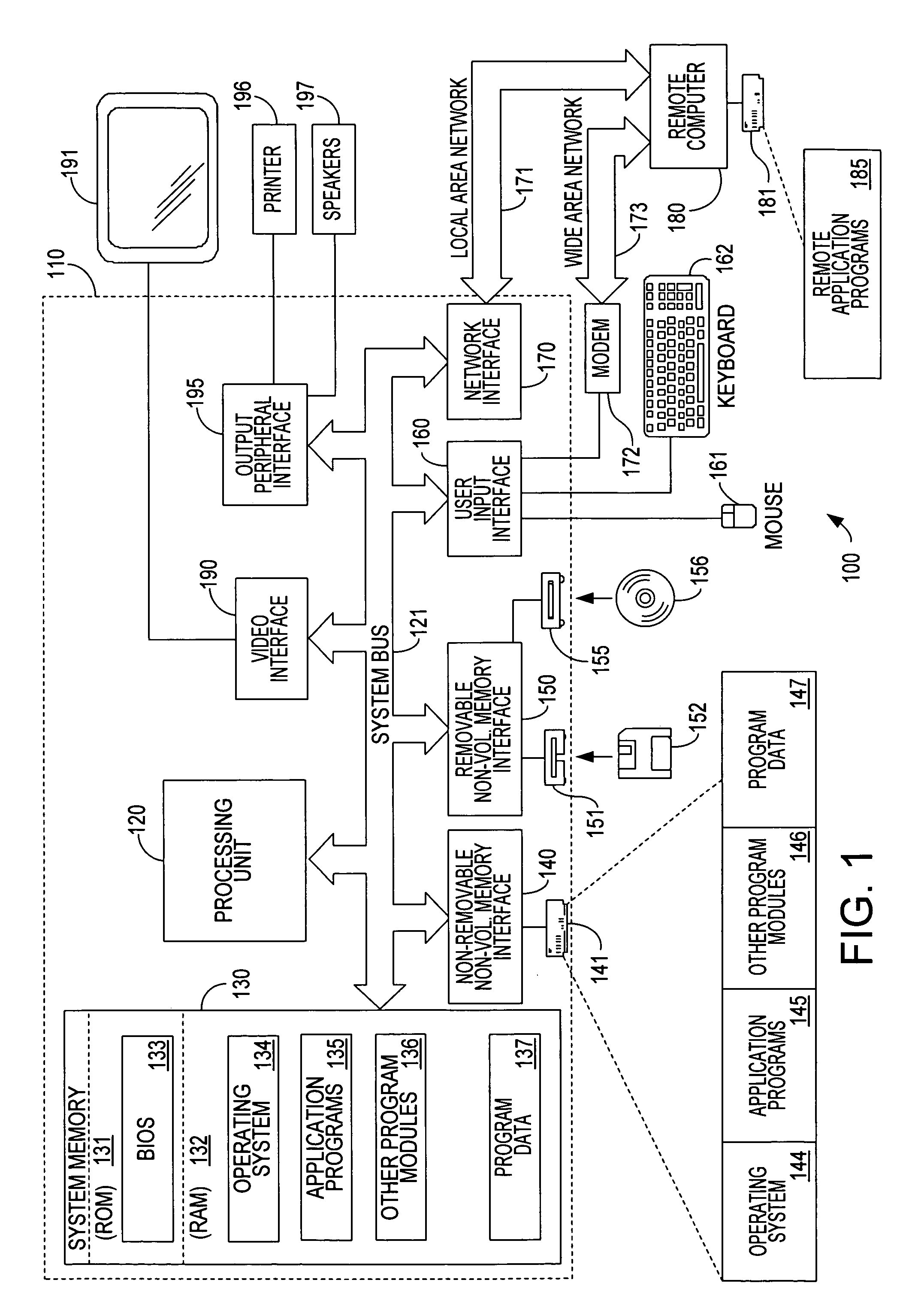
[0025] Turning to the drawings, wherein like reference numerals refer to like elements, the invention is illustrated as being implemented in a suitable computing environment. Although not required, the invention will be described in the general context of computer-executable instructions, such as program modules, being executed by a personal computer. Generally, program modules include routines, programs, objects, components, data structures, etc. that perform particular tasks or implement particular abstract data types. Moreover, those skilled in the art will appreciate that the invention may be practiced with other computer system configurations, including hand-held devices, multi-processor systems, microprocessor based or programmable consumer electronics, network PCs, minicomputers, mainframe computers, and the like. The invention may also be practiced in distributed computing environments where tasks are performed by remote processing devices that are linked through a communica...


PUM


Abstract

The distributed firewall performs user authentication at a first level to establish a user security context for traffic from that user, and an authority context provides authorization for subsequent traffic. This authority context may be based on an underlying policy for particular types of traffic, access to particular applications, etc. Additionally, the system includes the ability to allow a user/process/application to define its own access control. The linking of the user security context from the traffic to the application is accomplished by enabling IPSec on a socket and forcing the socket to be bound in exclusive mode. The most common policy definitions may be included by default. Extensions of the Internet key exchange protocol (IKE) to provide the desired user authentication plus application/purpose are also provided. The architecture includes pluggable authorization module(s) that are called after IKE has successfully authenticated the peer, but before the connection is allowed to complete.

Description

CROSS REFERENCE TO RELATED APPLICATION [0001] This application is a divisional of U.S. patent application Ser. No. 10 / 014,747, filed Oct. 26, 2001.FIELD OF THE INVENTION [0002] This invention relates generally to network firewall systems and, more particularly, to distributed firewall systems providing end point protection at each peer / server. BACKGROUND OF THE INVENTION [0003] Firewalls today are building highly sophisticated network protocol stacks for protocol and content analysis. Unfortunately, inspection points in the middle of the network are a choke point. That is to say, they do not enable communications to scale because they necessarily slow down end-to-end communication in order to inspect packets. At 100 Mbit, 1 Gbit, and 10 gigabit speeds, no single point can afford to do anything but route traffic into the destination network which spreads this aggregated load along successively smaller paths to reach end-systems. Such a prior architecture is illustrated in FIG. 7. As ...

Claims


Application Information

Patent Timeline
IPC IPC(8): G06F15/16H04L29/06
CPCH04L63/164H04L63/0218
Inventor DIXON, WILLIAM H.PALL, GURDEEP S.PALEKAR, ASHWINABOBA, BERNARD D.SWANDER, BRIAN D.
Owner MICROSOFT TECH LICENSING LLC
Why Eureka
Try Eureka