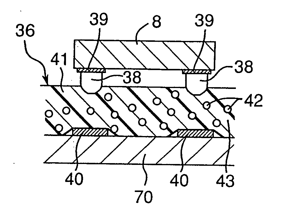
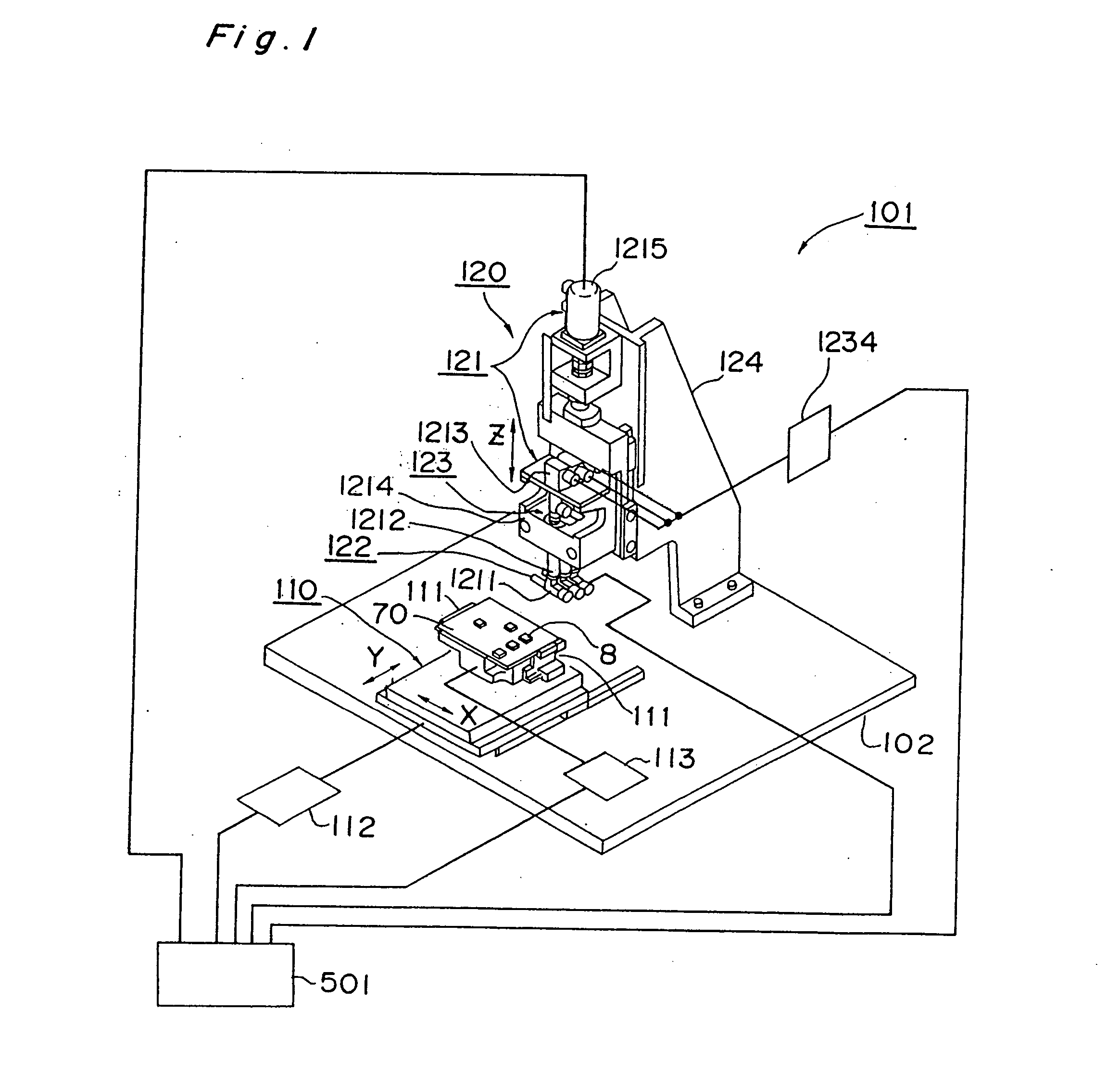
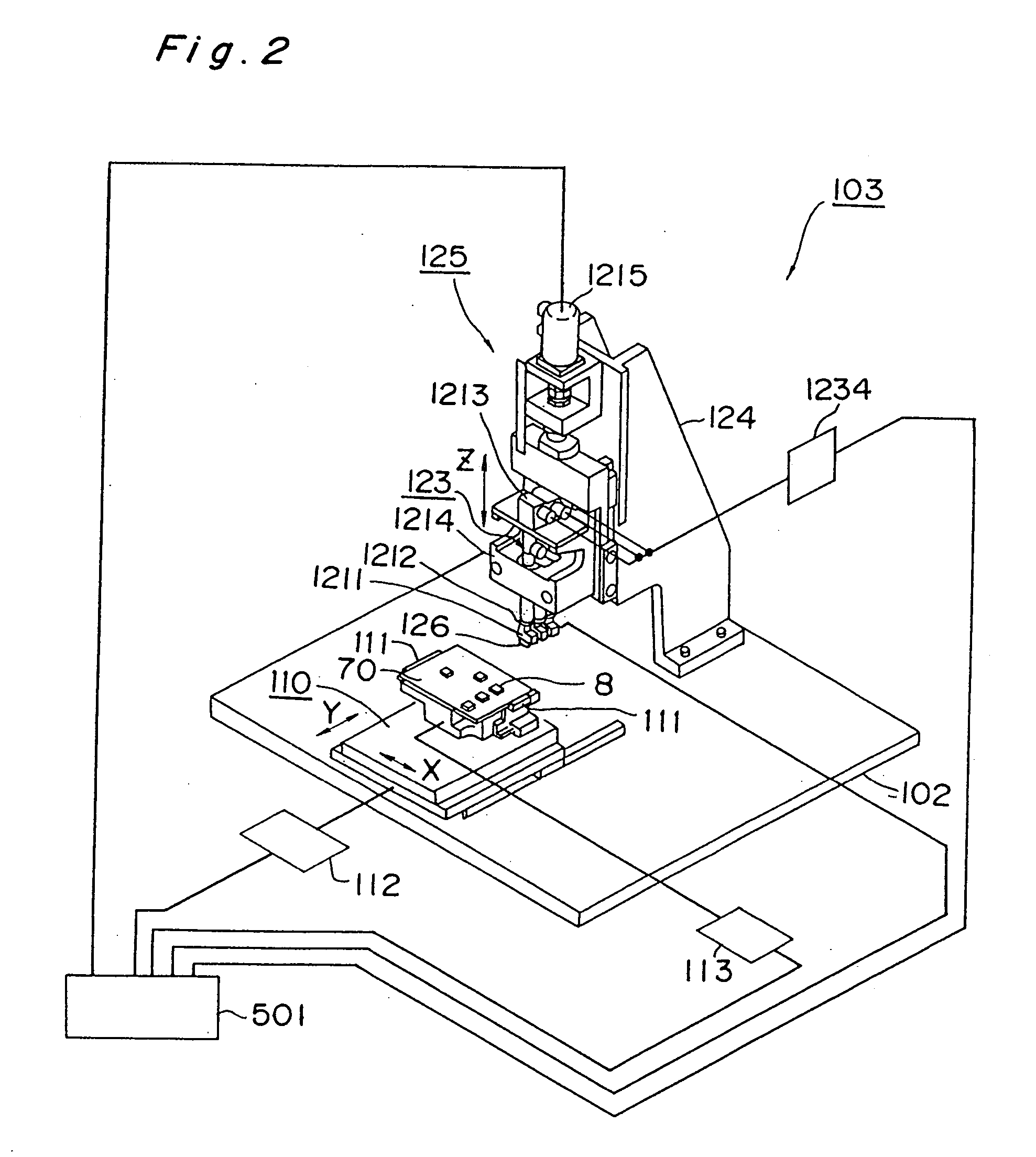
Heating and pressurizing apparatus for use in mounting electronic components, and apparatus and method for mounting electronic components

a technology for mounting electronic components and pressurizing apparatuses, which is applied in the field of heat and pressurizing apparatuses for mounting electronic components, can solve the problems of prolonging the time required for the whole mounting process, affecting and accelerating the rise of flip-chip mounting. achieve the effect of maximising the production cycle efficiency of the mounting apparatus and improving the productivity of the whole flip-chip mounting lin

Inactive Publication Date: 2006-01-26
PANASONIC CORP
View PDF7 Cites 0 Cited by
  • Summary
  • Abstract
  • Description
  • Claims
  • Application Information

AI Technical Summary

Benefits of technology

[0008] The present invention has been developed to solve such issues. Therefore, an object of the invention is to provide a heating and pressurizing apparatus for use in mounting electronic components, as well as an electronic component mounting apparatus equipped with the heating and pressurizing apparatus, and an electronic component mounting method. The present invention is capable of increasing to a maximum the production cycle efficiency of the mounting apparatus for flip-chip-mounting electronic components onto the circuit board, and of improving the productivity of the whole flip-chip mounting line.

Problems solved by technology

In addition, in SAW (Surface Acoustic Wave) devices used for mobile phones, the flip-chip mounting is also beginning to rapidly prevail.
However, for the flip-chip mounting technique, unlike the conventional mounting technique, various connection methods are available and the present situation is that companies in the art are employing various methods, while groping thereabout, in terms of intellectual property rights, reliability, and the like.
However, in the above conventional process, although electronic components can be flip-chip-mounted onto the circuit board with high precision and high speed in the flip-chip mounter, the production rate comes to an abrupt fall because the heating and pressurizing operation for curing the bonding element 9 is also executed in the flip-chip mounter, prolonging the time required for the whole mounting process.

Method used


Image

  • Heating and pressurizing apparatus for use in mounting electronic components, and apparatus and method for mounting electronic components
  • Heating and pressurizing apparatus for use in mounting electronic components, and apparatus and method for mounting electronic components
  • Heating and pressurizing apparatus for use in mounting electronic components, and apparatus and method for mounting electronic components

Examples


Embodiment Construction

[0037] Before the description of the present invention proceeds, it is to be noted that like parts are designated by like reference numerals throughout the accompanying drawings.

[0038] A heating and pressurizing apparatus for use in mounting electronic components, an electronic component mounting apparatus equipped with this heating and pressurizing apparatus for use in mounting electronic components, and an electronic component mounting method to be executed by using this heating and pressurizing apparatus for use in mounting electronic components, which are an embodiment of the present invention, are described below with reference to the accompanying drawings. Throughout the drawings, like component parts are designated by like reference numerals. In this embodiment, a flip-chip mounter is taken as an example for fulfilling the function of the pre-bonding unit.

[0039] The electronic component mounting apparatus 601, as shown in FIGS. 5 and 10, comprises a flip-chip mounter 301, a...


PUM

PropertyMeasurementUnit
pressurizing timeaaaaaaaaaa
production cycle timeaaaaaaaaaa
timeaaaaaaaaaa

Abstract

A heating and pressurizing apparatus (101), to which a circuit board (70) with electronic components (8) pre-bonded thereto via bonding elements (9) is carried in, is provided. The heating and pressurizing apparatus post-bonds the electronic component to the circuit board by heating and pressurizing the electronic component by a contact member (1211) having a heating device (122). By executing the pre-bonding and the post-bonding of the electronic components to the circuit board independently of each other, the time required for the post-bonding can be reduced, compared with the conventional case, and the productivity of the whole mounting line can be improved.

Description

[0001] This application is a Continuation Application of Ser. No. 10 / 365,515, filed on Feb. 13, 2003, which is a Divisional Application of Ser. No. 09 / 554,721, filed May 18, 2000, which is the National Stage Application of International Application No. PCT / JP98 / 05204, filed Nov. 19, 1998.TECHNICAL FIELD [0002] The present invention relates to a heating and pressurizing apparatus for use in mounting electronic components. Using the apparatus, an electronic component pre-bonded onto a circuit board in a flip chip manner via a bonding element that needs heating and pressurizing is pressurized and heated, thereby making the bonding element cured so that the electronic component is post-bonded. The invention also relates to an electronic component mounting apparatus equipped with the heating and pressurizing apparatus, as well as an electronic component mounting method. BACKGROUND ART [0003] In recent years, the flip-chip mounting of ICs has been rapidly becoming widespread with views to...

Claims


Application Information

Patent Timeline
Patent Type & Authority Applications(United States)
IPC IPC(8): B29C65/00H01L21/00H01L21/56
CPCH01L21/563Y10T29/53178H01L24/75H01L2224/1134H01L2224/16225H01L2224/73203H01L2224/73204H01L2224/83192H01L2924/01039H01L2924/01079H01L2924/14H05K13/0469H01L24/29H01L2924/01006H01L2924/01033H01L24/83H01L21/67144Y10T156/17Y10T29/53174Y10T156/1702Y10T156/16Y10T29/5313H01L2224/32225H01L2924/00H01L2224/13099H01L2924/01058H01L2924/00013H01L2224/05573H01L2224/05568H01L2924/00014Y10T156/1092Y10T29/49137Y10T29/4913Y10T156/1744Y10T156/1768H01L2224/75317H01L2224/05599
Inventor MINAMITANI, SHOZOHOSOTANI, NAOTOMORITA, KOICHIONOBORI, SYUNJINISHINO, KENICHI
Owner PANASONIC CORP
Why Eureka
Try Eureka