Fluid agitating fin, method of fabricating the same and heat exchanger tube and heat exchanger or heat exchanging type gas cooling apparatus inwardly mounted with the fin

a technology of agitating fins and fins, which is applied in the direction of lighting and heating apparatus, machines/engines, laminated elements, etc., can solve the problems of insufficient function and achieve the effect of effective agitation, excellent cooling efficiency and efficient promotion

Inactive Publication Date: 2006-01-26
USUI KOKUSAI SANGYO KAISHA LTD
View PDF6 Cites 67 Cited by
  • Summary
  • Abstract
  • Description
  • Claims
  • Application Information

AI Technical Summary

Benefits of technology

[0018] When the fluid agitating plate fin according to the present invention is mounted to the inside or the outside of the heat exchanger tube in which the cooled medium or the cooling medium flows, the blade edges of plate fins are butted to be opposed to each other upward and downward, the respective butted blade edges are integrated to cross each other and therefore, the fluid comprising a gas or a liquid flowing at the inside or the outside of the heat exchanger tube brings about the turbulent flow or the vortex flow by complicatedly agitating flowing lines thereof, the laminar flow is exfoliated and effective agitation is repeated. Therefore, the fluid flowing at the inside or the outside of the heat exchanger tube is repeatedly brought into contact with the wall face of the heat exchanger tube, heat exchange with the cooling medium or the cooled medium at the outer peripheral face of the heat exchanger tube is efficiently promoted and the excellent cooling efficiency is ensured. Further, according to the heat exchanger of the invention arranged with at least one piece of the heat exchanger tube according to the present invention inwardly mounted with the plate fin, the fluid flowing in the heat exchanger tube is repeatedly brought into contact with the wall face of the heat exchanger tube, heat exchange to the cooling medium at the outer peripheral face of the heat exchanger tube is efficiently promoted and the excellent cooling efficiency is ensured. Further, the method of fabricating the fluid agitating plate fin according to the present invention is by extremely simple working means of forming the plurality of plate fins at the surface of the plate material by forming the plurality of predetermined notched portions at the plate material comprising the thin plate and raising the remaining notched portions of the notched portions orthogonally to the surface of the plate material, in addition thereto, also in integrating the plate fin to the heat exchanger tube, the plate fin can easily be mounted inwardly not only to the flat heat exchanger tube but also a circular tube or a deformed tube and therefore, the plate fin can preferably be mounted as the fluid agitating plate fin mounted to the inside or the outside of the heat exchanger tube of not only the heat exchange type cooling apparatus but also a heat exchanger of a cooler for a fuel, an oil cooler, an intercooler or the like and at the same time, by the excellent heat exchange function and by forming the core by the plate fin per se, the plate fin contributes to solid formation of the apparatus to enable to constitute the small-sized and light-weighted formation, compact formation of the apparatus is realized and the apparatus can easily be installed in a limited space.

Problems solved by technology

Although the background arts are devised to promote an increase in the heat exchange efficiency by forcibly bringing about a turbulent flow or a vortex flow in the cooled medium flowing in the heat exchanger tube by forming recesses or projections or wrinkles directly on the inner face of the heat exchanger tube or inwardly mounting the plate fin or the baffle in various shapes thereto, whereas difficulties are required in working or attaching method thereof, the sufficient function cannot be achieved to pose a serious problem desired to improve further.

Method used


Image

  • Fluid agitating fin, method of fabricating the same and heat exchanger tube and heat exchanger or heat exchanging type gas cooling apparatus inwardly mounted with the fin
  • Fluid agitating fin, method of fabricating the same and heat exchanger tube and heat exchanger or heat exchanging type gas cooling apparatus inwardly mounted with the fin
  • Fluid agitating fin, method of fabricating the same and heat exchanger tube and heat exchanger or heat exchanging type gas cooling apparatus inwardly mounted with the fin

Examples


embodiment 1

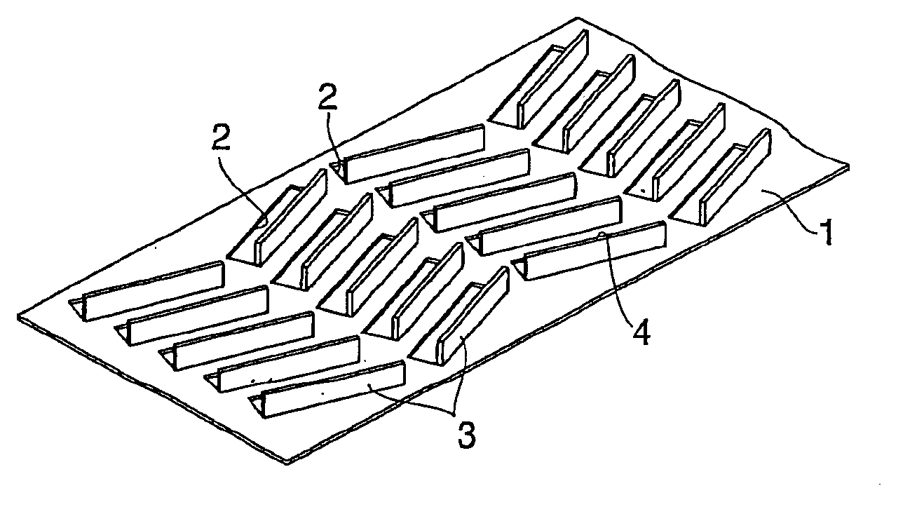
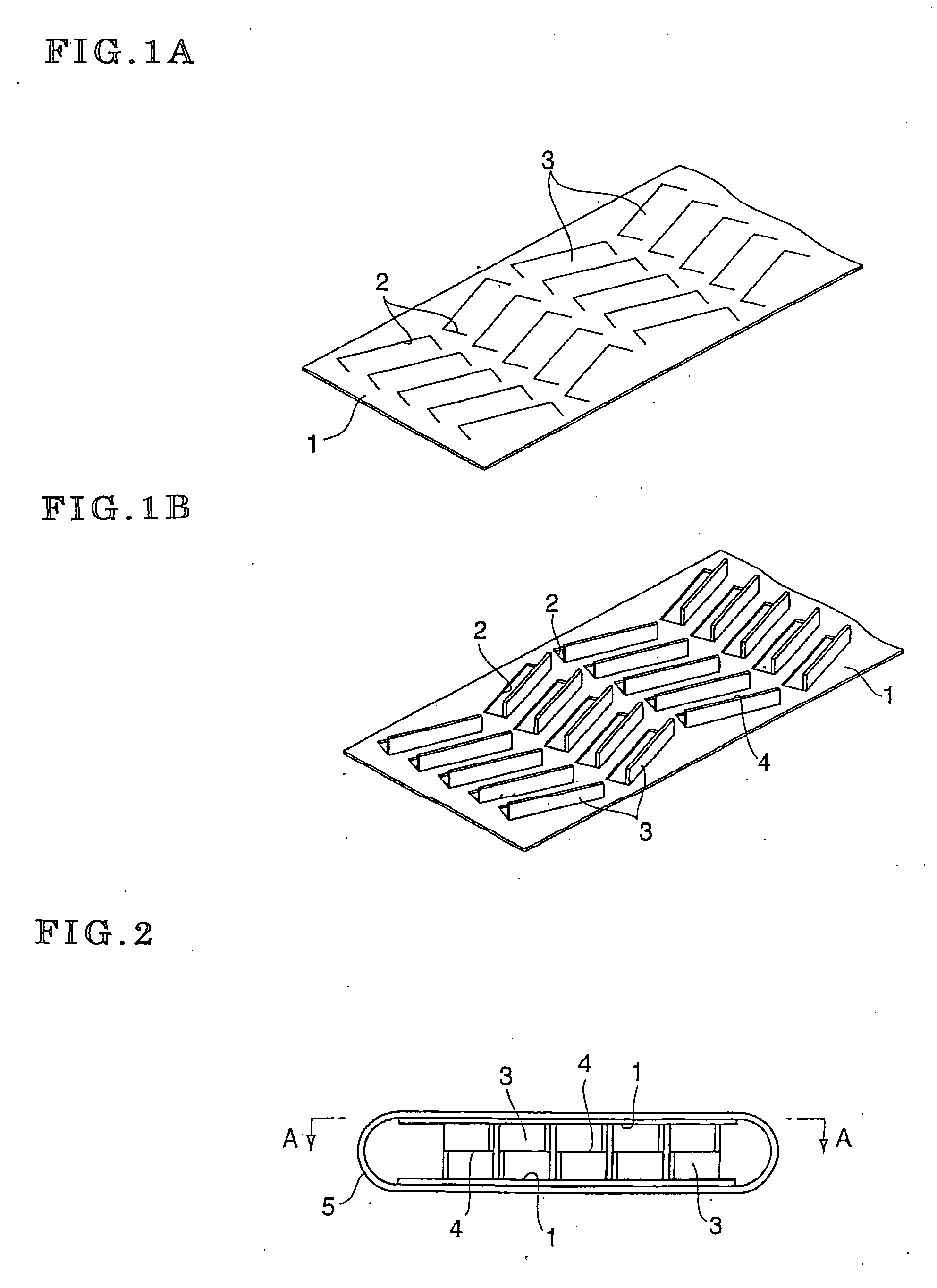
[0046] According to a fluid agitating plate fin 3 according to a first embodiment of the invention, as shown by FIG. 1, thin plates comprising austenite species stainless steel of SUS 304, SUS 316 or the like having a thickness of about 0.1 through 0.5 mm are worked in a rectangular shape having a predetermined dimension to provide a plurality of plate materials, two sheets of the plate materials are pressed to form a plurality of notched portion 2 substantially in a channel-like shape having a predetermined dimension directions of which alternately differ as shown by FIG. 1A. Next, remaining notched portions of the notched portion 2 are cut to be raised to be orthogonal to a surface of the plate member to provide a plate 1 formed with fluid agitating plate fins 3 directions of which differ alternately at respective rows and blade edge 4 of which are constituted by linear lines inclined to a longitudinal direction. Thereafter, by preparing two sheets of the provided plates 1 and but...

embodiment 2

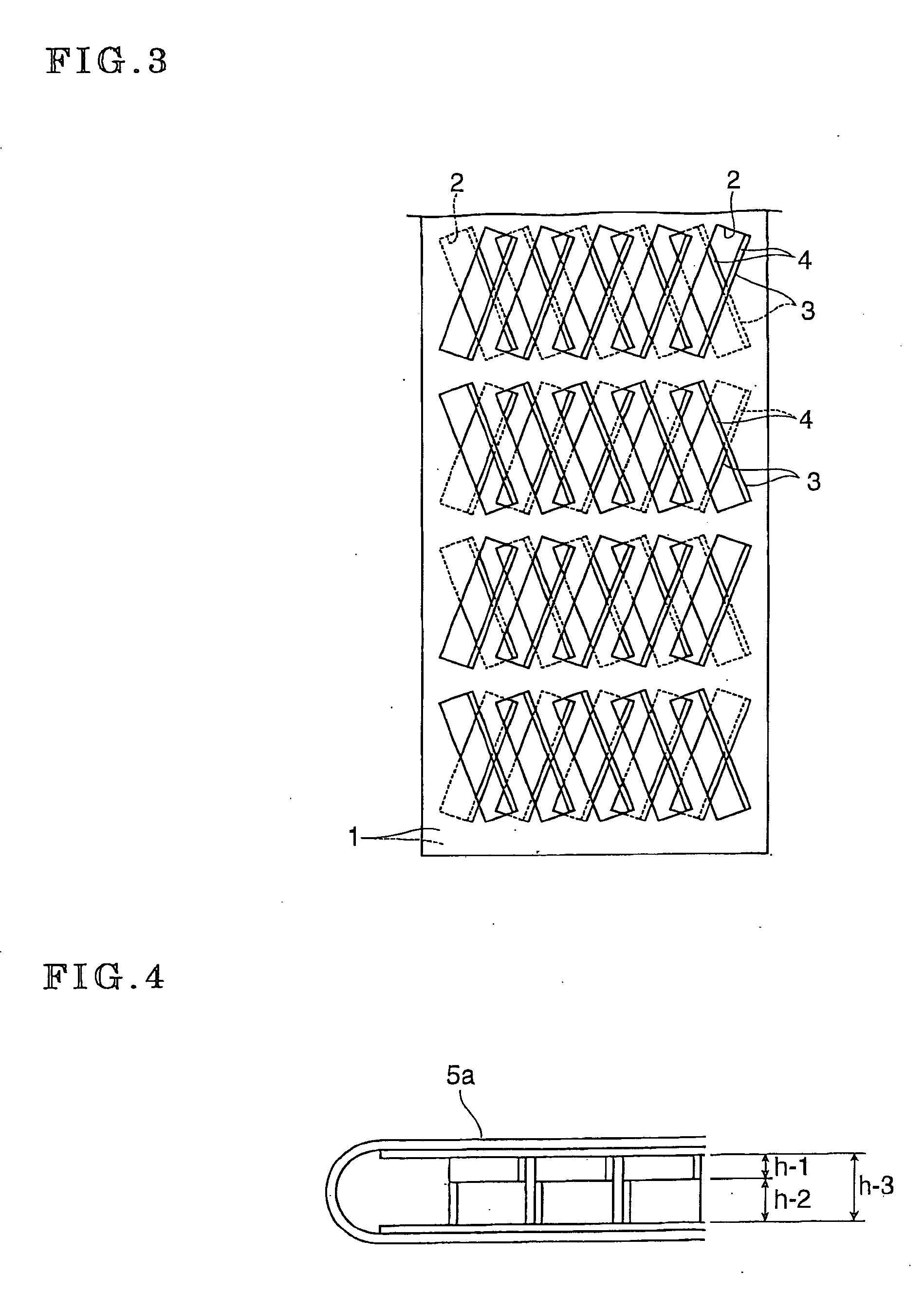
[0048] There is provided a fluid agitating plate fin 3a as shown by FIG. 5B similar to embodiment 1 except that a plate material constituted by connecting two sheets of the plate materials in Embodiment 1 in a longitudinal direction is prepared, predetermined notched portions are provided at plate materials on the left and on the right of a boundary of a center folding portion 1a-3, a fluid agitating fin 3a as shown by FIG. 5A is formed after raising remaining notched portions of the outer notched portions, thereafter, the plate material is folded at the center folding portions 1a-3, and respective blade edges 4a of the fluid agitating fins 3a formed at a plate 1 (1a-1) and a plate 2 (1a-2) are butted to be opposed to each other, a heat exchanger tube inwardly mounted with the plate fin 3a is finished similar to Embodiment 1 to be subjected to a cooling test by an EGR gas cooling apparatus (shell and tubes type heat exchanger) similar to Embodiment 1, as a result, it is confirmed th...

embodiment 3

[0049] A fluid agitating plate fin 3b is provided similar to Embodiment 1 except that a shape of the fluid agitating plate fin formed to a plate material is formed by bending a shape of a blade edge 4b in a longitudinal direction in place of the fluid agitating plate fins 3 and 3a provided by Embodiment 1 or Embodiment 2, and when a heat exchanger tube inwardly mounted with the fluid agitating fin 3b is constituted by using the fin 3b and is mounted to an EGR gas cooling apparatus to be subjected to a cooling test similar to Embodiment 1, it is confirmed that a cooling efficiency is further increased in comparison with that of Embodiment 1.


PUM


Abstract

A fluid agitating plate fin is mounted to a heat exchanger tube to agitate a cooling fluid and to create a turbulent flow. Edges of the plate fins are opposed to each other and the opposed butted blade edges cross each other.

Description

BACKGROUND OF THE INVENTION [0001] 1. Field of the Invention [0002] The present invention relates to a structure of a fin for agitating a fluid in a heat exchanger, particularly, relates to a fluid agitating plate fin mounted to inside or outside of a heat exchanger tube in a heat changing type cooling apparatus and achieving an excellent heat exchanging function by increasing contact between a wall face of a heat exchanger tube and a fluid by bringing about an agitating operation of a turbulent flow or a vortex flow in the fluid comprising a cooled medium or a cooling medium flowing inside or outside of the heat exchanger tube, a method of fabricating the plate fin as well as a heat exchanger tube inwardly mounted with the plate fin and a heat exchanger or a heat exchanging type gas cooling apparatus constituted by being arranged with at least one piece of the heat exchanger tube. [0003] 2. Description of Related Art [0004] In recent years, starting from an EGR cooler for recircula...

Claims


Application Information

Patent Timeline
Patent Type & Authority Applications(United States)
IPC IPC(8): F28F13/12
CPCF02M25/0737F28D7/1684F28D21/0003Y02T10/121F28F3/02F28F13/12F28F1/40F02M26/32
Inventor HASHIMOTO, YASUAKIGOTO, TADAHIRO
Owner USUI KOKUSAI SANGYO KAISHA LTD
Why Eureka
Try Eureka