Fluid filter system and related method

a filter system and flue gas technology, applied in the field of systems, can solve the problems of increased strain on existing water transfer and treatment infrastructure, increased likelihood of natural water contamination, and increased pollution, and achieve the effects of maximizing contaminant retention, reducing the probability of natural water contamination, and reducing the number of contaminated areas

Active Publication Date: 2006-01-26
CONTECH ENGINEERED SOLUTIONS +1
View PDF98 Cites 42 Cited by
  • Summary
  • Abstract
  • Description
  • Claims
  • Application Information

AI Technical Summary

Benefits of technology

[0012] It is an object of the present invention to provide a separation system that is effective in accommodating varied fluid flow rates. It is also an object of the present invention to provide such a separation system that conforms or substantially conforms with established contaminant removal requirements. Further, it is an object of the present invention to provide such a separation system that is cost effective and configured for ease of maintenance. In that regard, it is an object of the present invention to maximize contaminant retention within the system while minimizing retention on the surface of the filter and to reduce filter device weight at the time of maintenance activities. The separation system preferably includes a filter system capable of removing identified contaminants with minimal impact on fluid flow rates.

Problems solved by technology

If such diversion or treatment systems are not provided, particulate and contaminants located on or forming part of such structures may be carried by drain water or stormwater to the natural water bodies and contaminate them.
Land development produces increased quantities of drain water and stormwater runoff, resulting in increased strain on existing water transfer and treatment infrastructure and an increased likelihood of natural water contamination.
Swales and settling ponds take up significant real estate and are therefore generally not particularly desirable in many settings.
The separators require less space to operate, but are relatively costly and require considerable servicing on a regular basis.
Existing absorbers and filter mechanisms may be effective at removing specified contaminants; however, they tend to do so at the expense of flow through rates.
That is, the filtration efficiency is relatively low in comparison to the required water flow through desired.
However, it is important that the separation systems not be prohibitively expensive in order to ensure that meeting those needs and requirements is feasible.
Fluid filter systems that are configured to allow for loading of the filter by all floating and nonfloating particulates require maintenance over relatively short intervals.
In subsequent fluid treatment cycles, contaminants that remain caked-on the filter surface reduce fluid flow through effectiveness and must therefore be removed relatively frequently.
In addition, wet, caked filters are very heavy and therefore require the use of assistive equipment, such as cranes, when they are to be removed for maintenance.

Method used


Image

  • Fluid filter system and related method
  • Fluid filter system and related method
  • Fluid filter system and related method

Examples


Embodiment Construction

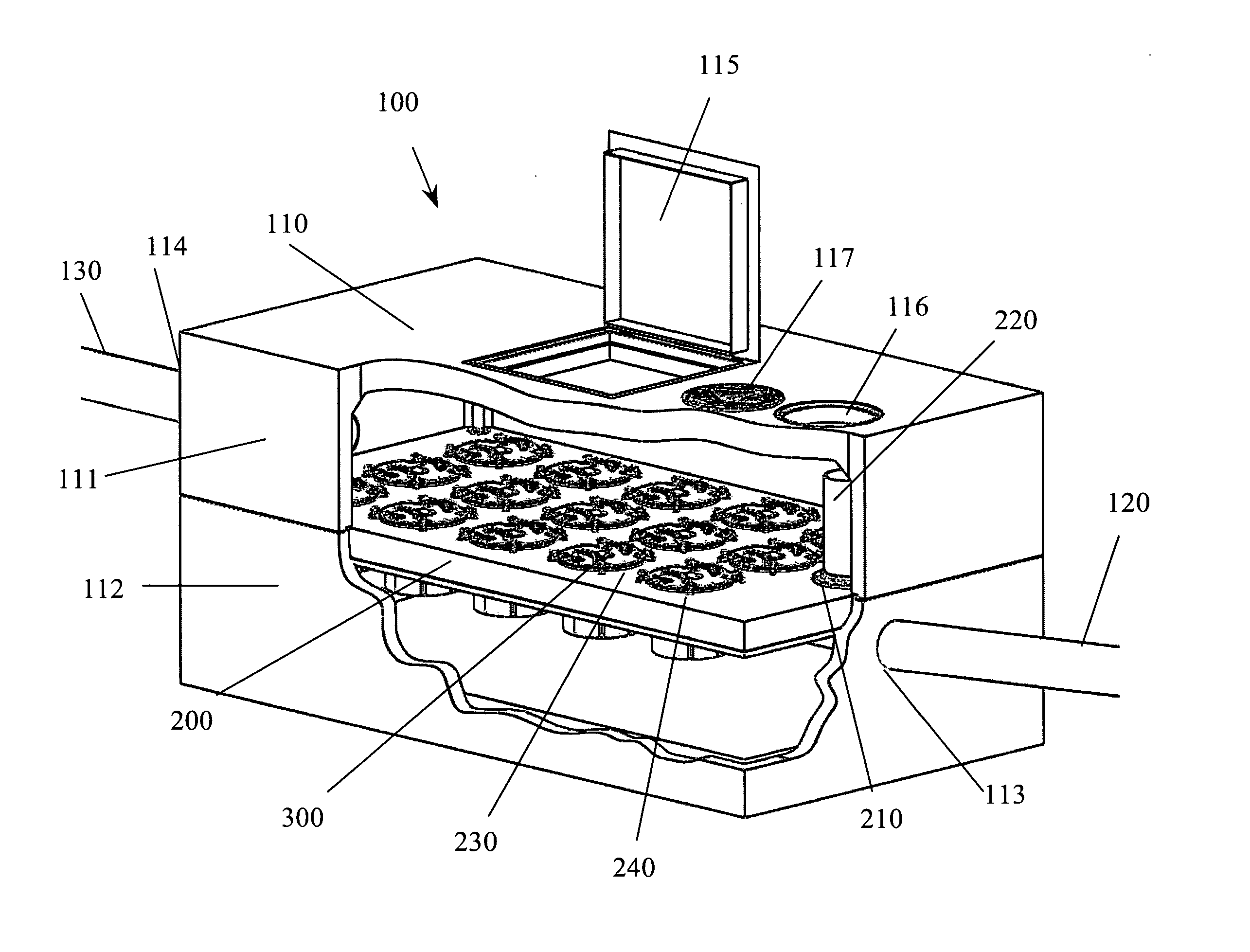
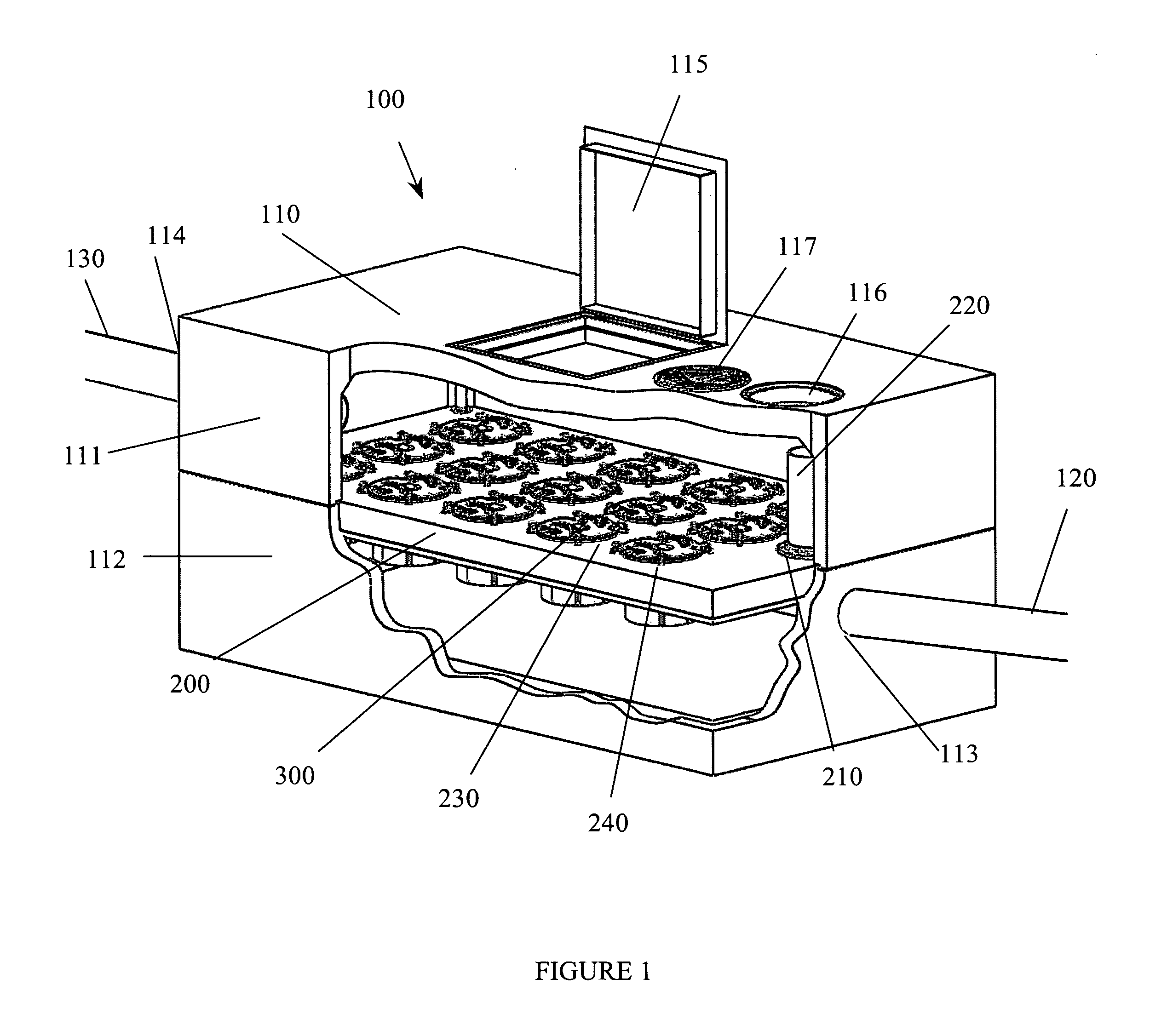
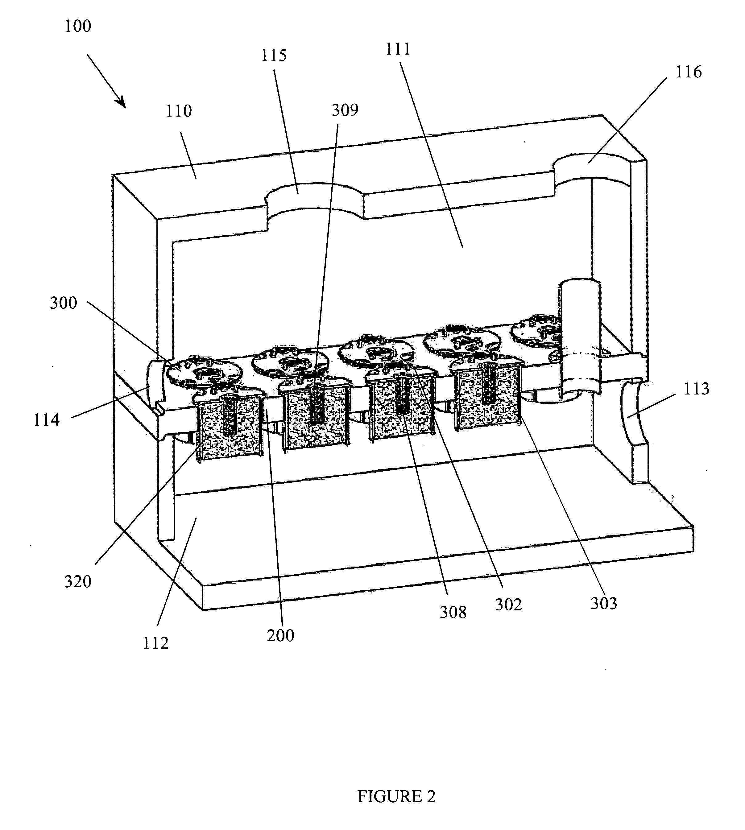
[0036] A separation system 100 of the present invention is illustrated in the accompanying drawings. As shown in FIGS. 1-3, the system 100 includes a tank 110 having an outflow chamber 111 and a containment chamber 112 spaced below the outflow chamber 111 by a confinement deck 200. The containment chamber 112 includes a tank inlet port 113 through which a fluid to be treated enters the containment chamber 112 from an inlet conduit 120. The outflow chamber 111 includes a tank outlet port 114 through which a treated fluid exits the outflow chamber 111 via an outlet conduit 130. The tank 110 also preferably includes an access hatch 115 for accessing the interior of the tank 110 at the outflow chamber 111, and a manhole 116 with cover 117. While the preferred embodiment of the present invention describes the separation system 100 with a specific outflow chamber 111 above the confinement deck 200, it is to be understood that in an alternative embodiment, the fluid may pass from the conta...


PUM

PropertyMeasurementUnit
flow rateaaaaaaaaaa
perimeteraaaaaaaaaa
flow ratesaaaaaaaaaa

Abstract

A system and related method for separating floating and nonfloating particulate and entrained, suspended, and/or dissolved contaminants from a fluid. The system includes a tank with a lower chamber spaced from an outlet or upper chamber by a confinement deck. The deck includes one or more sockets for receiving one or more filter units for fluid treatment. In addition, the lower chamber of the tank acts as a pretreatment sump to remove floating and nonfloating particulates, thereby reducing the load on the filter units. The filter units are configured for radial and/or upward flow of the fluid from the lower chamber. The filter units may include one or more filter media through which the fluid pass prior to exiting the tank. The filter units include a removable screening retainer for retaining the filter media and/or to screen relatively large contaminants. The filter unit may be removed for ease of tank maintenance and replacement of filter media. The system allows a method of contaminated fluid treatment under varying flow conditions by directing the fluid radially and/or upwardly through the retainer. Establishing both types of flow through the filter unit improves filtering and extends filter life without compromising desired flow through rates.

Description

CROSS REFERENCE TO RELATED APPLICATION [0001] The present application claims the priority benefit of U.S. provisional patent application Ser. No. 60 / 590,776, filed Jul. 23, 2004, entitled “FLUID FILTER SYSTEM AND RELATED METHOD” of the same named inventors. The entire contents of that prior application are incorporated herein by reference.BACKGROUND OF THE INVENTION [0002] 1. Field of the Invention [0003] The present invention relates to systems for filtering contaminants from fluids such as drain water and stormwater. More particularly, the present invention relates to a filter system and related method for removing contaminants from a fluid stream by forcing upward and / or radial flow of the fluid through the filter means. [0004] 2. Description of the Prior Art [0005] Fluid transfer systems have been and will remain an important aspect of municipal services and commercial facilities management. The protection of ground water and natural bodies of water requires systems for divertin...

Claims


Application Information

Patent Timeline
Patent Type & Authority Applications(United States)
IPC IPC(8): B01D29/00
CPCB01D29/15B01D35/027E03F5/14B01D29/52B01D29/96B01D35/04B01D29/00
Inventor OLSON, NORMAN L.MCLAUGHLIN, BRIAN R.COBB, DANIEL P.ALLEN, VAIKKO P. IIBERG, DEREK M.
Owner CONTECH ENGINEERED SOLUTIONS
Why Eureka
Try Eureka