Distributed active transformer power control techiques

a technology of active transformers and power control circuits, applied in gain control, phase splitters, instruments, etc., can solve problems such as undesirable harmonic distortion, large devices, and higher substrate loss

Active Publication Date: 2006-01-26
AXIOM MICRODEVICES
View PDF10 Cites 17 Cited by
  • Summary
  • Abstract
  • Description
  • Claims
  • Application Information

AI Technical Summary

Benefits of technology

[0009] Those skilled in the art will further appreciate the advantages and superior features of the invention together

Problems solved by technology

While the power control actuation circuits can be provided with a low on-resistance to reduce the power loss on it, such devices are typically large and use more surface area of an integrated circuit.
Large device size can results in a large parasitic

Method used


Image

  • Distributed active transformer power control techiques
  • Distributed active transformer power control techiques
  • Distributed active transformer power control techiques

Examples


Embodiment Construction

[0032] In the description that follows, like parts are marked throughout the specification and drawings with the same reference numerals, respectively. The drawing figures might not be to scale, and certain components can be shown in generalized or schematic form and identified by commercial designations in the interest of clarity and conciseness.

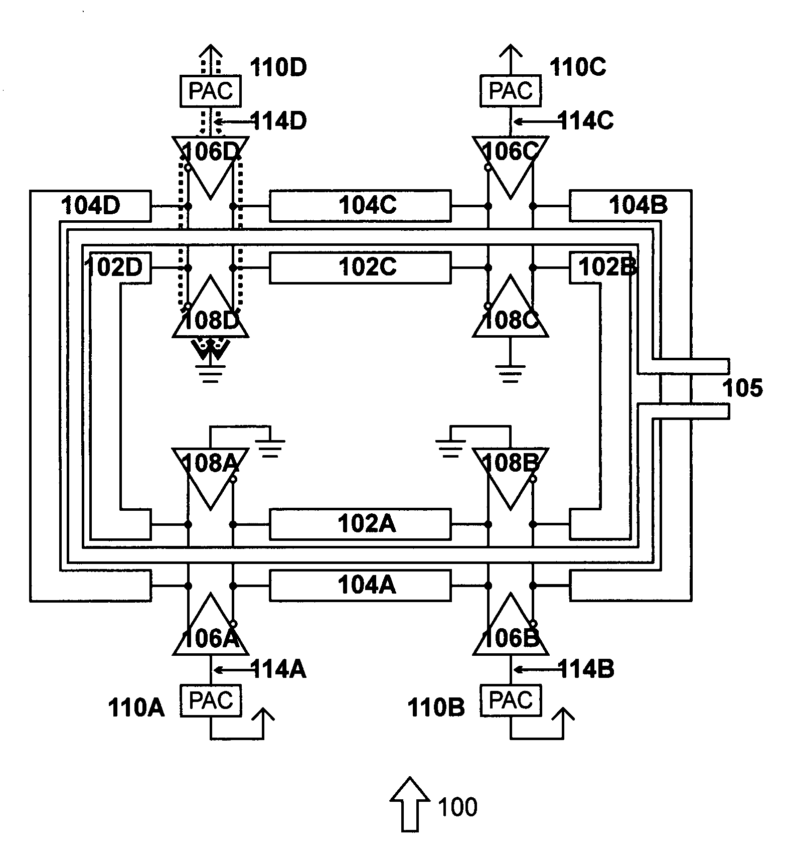
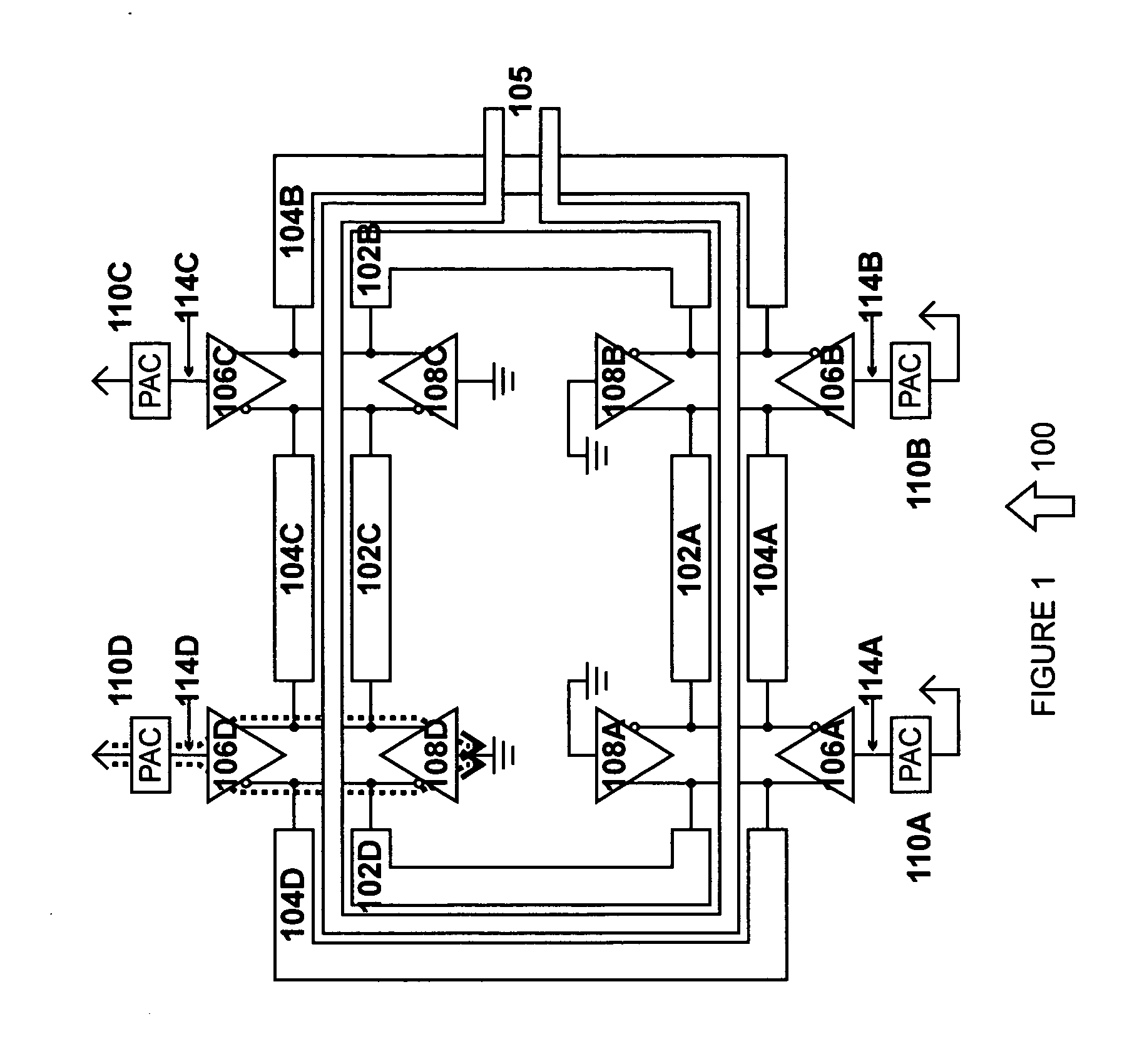
[0033] When “top” or other relative directional connotation is used in this context, it refers to the relative location of the power control actuation circuits in the dc current path from Vdd to dc ground. This directional notation should be treated separately from “inner” and “outer” notations which typically refer to the relative placement with regard to a DAT secondary. Generally, the choice of connecting a circuit to the “inner” or the “outer” primary can be treated as an independent decision as to whether the circuit should be connected to the “top” part of the supply or the “bottom”.

[0034]FIG. 1 is a diagram of a DAT 100 with power ...


PUM


Abstract

A distributed active transformer on a semiconducting substrate is provided. The distributed active transformer includes an outer primary, a secondary disposed adjacent to the outer primary, and an inner primary disposed adjacent to the outer primary and the secondary. A plurality of first three terminal devices is coupled to the outer primary at a plurality of locations. A plurality of second three terminal devices coupled to the inner primary at a plurality of locations, and each second three terminal device is disposed opposite from and coupled to one of the plurality of first three terminal devices. A plurality of power control actuation circuits is also provided, where each power control actuation circuit is coupled to one of the first three terminal devices and the second three terminal devices.

Description

RELATED APPLICATIONS [0001] This application claims priority to U.S. Provisional application 60 / 558,179, filed Mar. 31, 2004, which is hereby incorporated by reference for all purposes.FIELD OF THE INVENTION [0002] The present invention relates to distributed active transformers (DATs), and more specifically to power control actuation circuits for DATs that provides advantages for DAT operation. BACKGROUND [0003] Power control is required in most power amplifier applications. This is typically accomplished through the use of power control actuation circuits between the power supply and the power amplifier core, such as a two level push-pull P and N amplifier configuration. For different power levels, the top and bottom amplifying entities will experience different dc and ac signal levels as a function of the power control voltage. These ac and dc signal levels must be carefully controlled to avoid potentially damaging voltage levels. [0004] By adjusting the voltage drop across the p...

Claims


Application Information

Patent Timeline
IPC IPC(8): H01F27/28H01F27/00H03F3/26H03F3/60
CPCG01R15/09H03G3/3047H03F1/52H03F3/19H03F3/26H03F3/45475H03F3/602H03F3/604H03F3/605H03F2200/435H03F2200/451H03F2200/456H03F2200/462H03F2200/471H03F2200/541H03G3/004H03G3/3042G01R21/01
Inventor MAGOON, RAHULKEE, SCOTTAOKI, ICHIROCARR, FRANKWU, HUITWOMEY, JERRYHAJIMIRI, SEYED-ALI
Owner AXIOM MICRODEVICES
Why Eureka
Try Eureka