Image forming apparatus, image forming method and data control device

a technology of image forming apparatus and data control device, which is applied in the direction of electrographic process apparatus, instruments, printing, etc., can solve the problems of color registration offset, skew where, and image quality degradation, and achieve high quality, high accuracy, and increase the accuracy of color registration offset correction.

Inactive Publication Date: 2006-01-26
SEIKO EPSON CORP
View PDF15 Cites 21 Cited by
  • Summary
  • Abstract
  • Description
  • Claims
  • Application Information

AI Technical Summary

Benefits of technology

[0015] However, in the conventional apparatus described above, because the adjustment is made by mechanically moving a part of the components of the exposure unit such as an optical box in which the polygon mirror is placed, there is a certain limit in adjustment accuracy and it is practically impossible to accomplish the adjustment with accuracy of one pixel or less. Hence, there is a demand for a technique of further increasing the accuracy of the correction of the color registration offset thereby enabling the formation of images of high quality.
[0016] Further, as an image forming apparatuses which forms a color image, there is also known an image forming apparatus of a so-called four-cycle system besides the aforementioned tandem system. In this image forming apparatus, a process to form a latent image on a photosensitive member by the light beam scanning thereon, and to transfer onto a transfer medium such as an intermediate transfer belt a toner image which is obtained by developing the latent image with toner, is repeated for the respective four colors (yellow, magenta, cyan and black), and then these toner images of the four colors are mutually superimposed on the transfer medium, thereby forming the color image. In such an apparatus, as well, the correction of the color registration offset by way of the high accuracy adjustment of the respective forming positions of the latent images of the individual color components, or registration correction, is quite important for ensuring the formation of high quality images.
[0017] The present invention has been made in view of the foregoing problem. It is a second object of the invention to provide a technique of easily adjusting the position of the linear latent image formed on the latent image carrier with high accuracy for ensuring the formation of high quality images in an apparatus including a latent image forming unit which forms a linear latent image by a light beam which scans on a latent image carrier.

Problems solved by technology

This results in a degraded image quality.
One of the major causative factors of the color registration offset is the occurrence of skew where scanning lines are skewed relative to a reference line which is set in advance.
However, there may be a case where the scanning line in each of the exposure unit is skewed relative to the reference line, resulting in the occurrence of the color registration offset.
However, in the conventional apparatus described above, because the adjustment is made by mechanically moving a part of the components of the exposure unit such as an optical box in which the polygon mirror is placed, there is a certain limit in adjustment accuracy and it is practically impossible to accomplish the adjustment with accuracy of one pixel or less.

Method used


Image

  • Image forming apparatus, image forming method and data control device
  • Image forming apparatus, image forming method and data control device
  • Image forming apparatus, image forming method and data control device

Examples


first embodiment

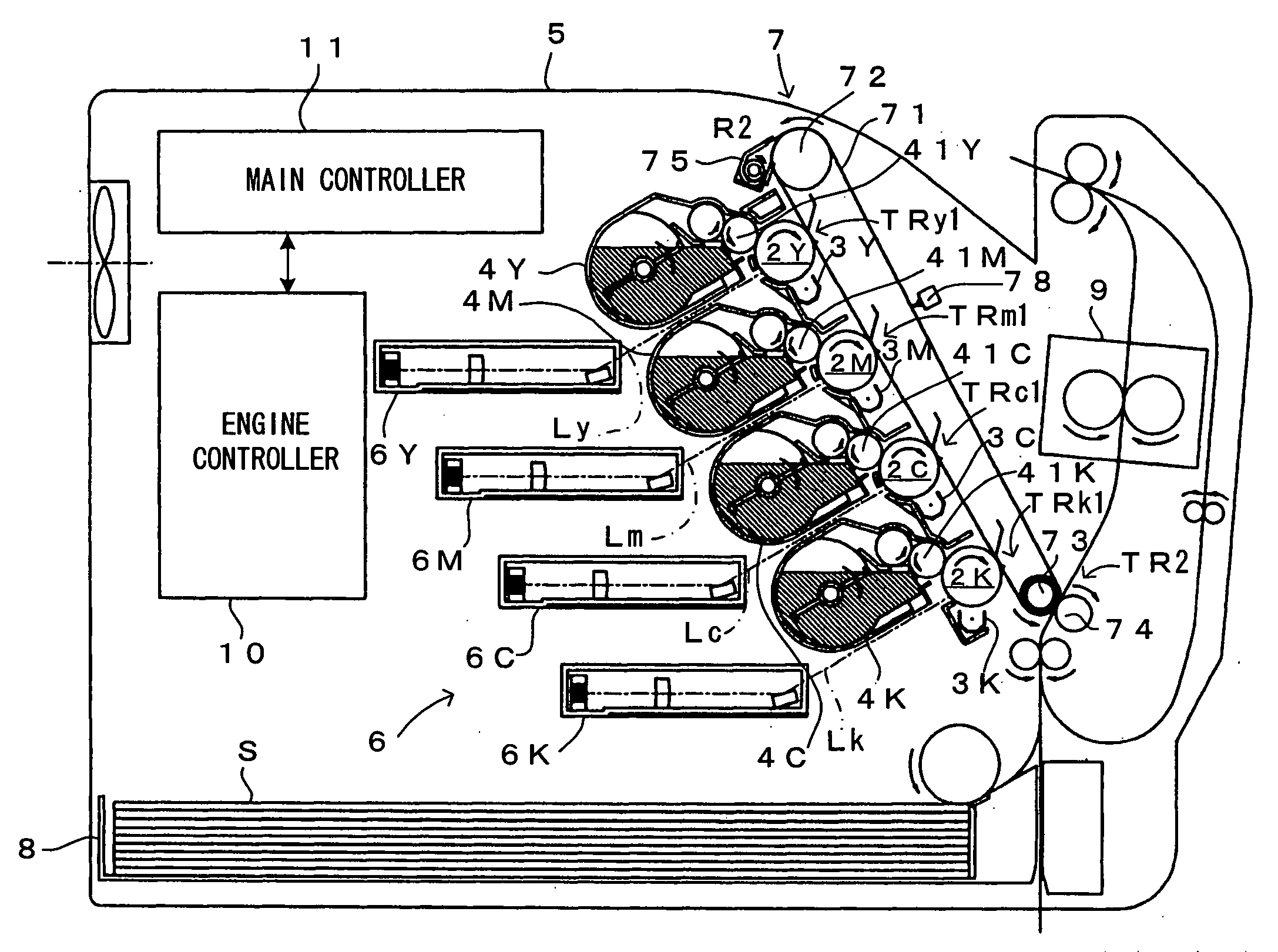
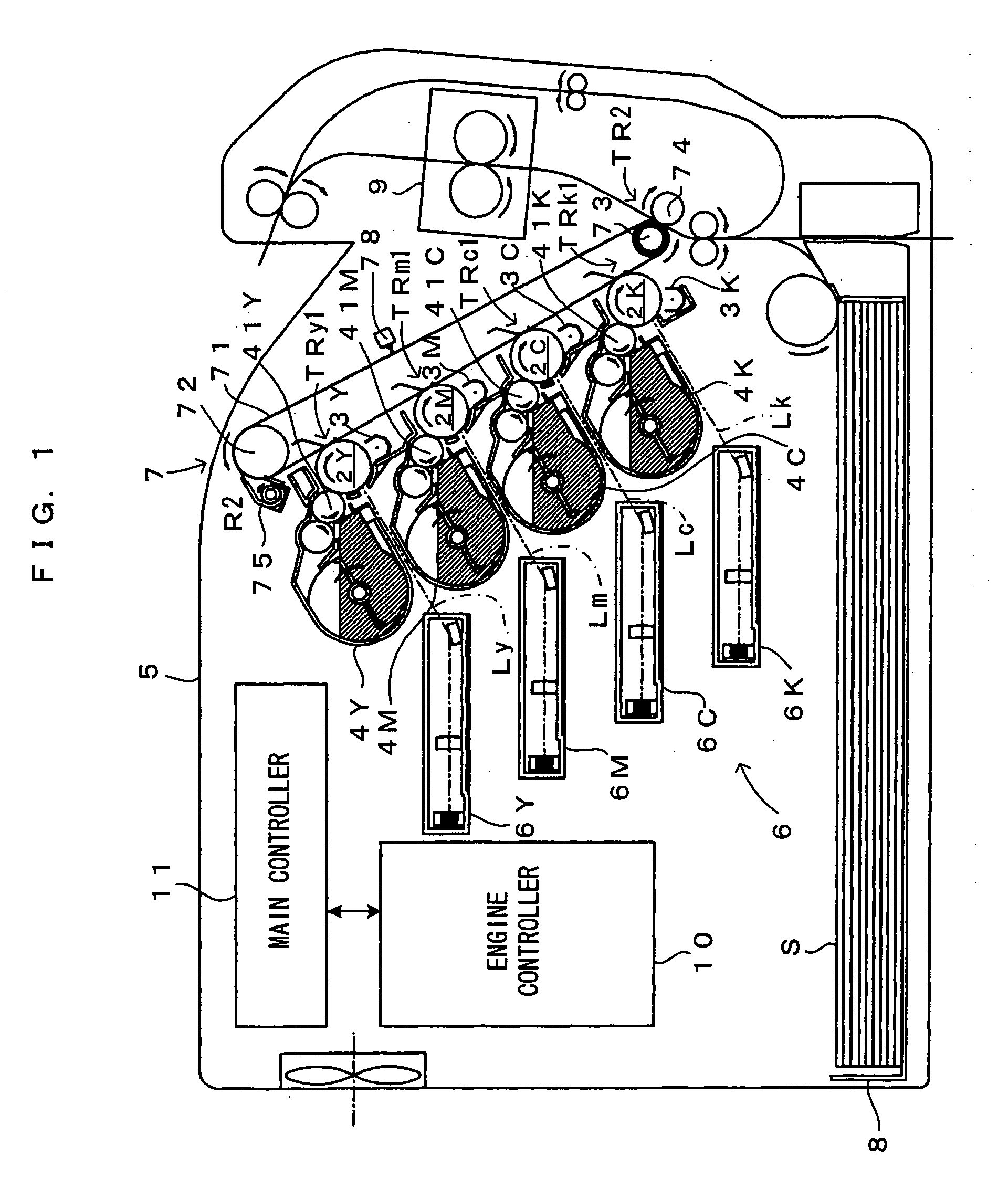
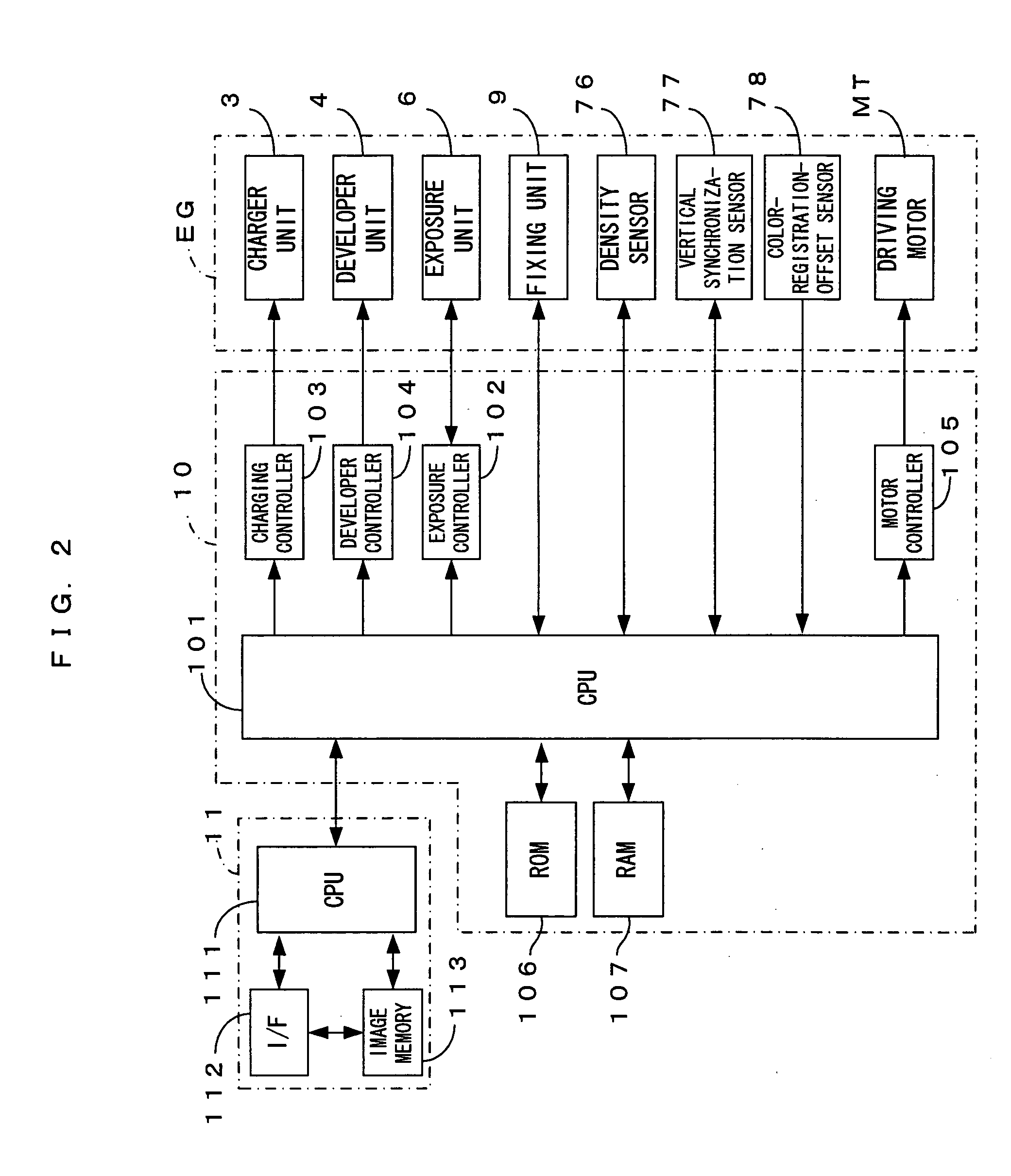
[0078]FIG. 1 is a diagram showing an image forming apparatus according to a first embodiment of the invention. FIG. 2 is a block diagram showing an electrical structure of the image forming apparatus shown in FIG. 1. This image forming apparatus is a so-called tandem color printer, wherein photosensitive members 2Y, 2M, 2C, 2K for four colors of yellow (Y), magenta (M), cyan (C) and black (K), as latent image carriers, are juxtaposed to each other in an apparatus body 5. The apparatus serves to form a full color image by superimposing toner images on the individual photosensitive members 2Y, 2M, 2C, 2K, or to form a monochromatic image using only the toner image of black (K). The image forming apparatus operates as follows. When an external apparatus such as a host computer applies a print command to a main controller 11 in response to a request from a user wanting to form an image, a CPU 111 of the main controller 11 sends a print command, based on which an engine controller 10 con...

second embodiment

[0109]FIG. 9 is a block diagram showing an electric structure of an image forming apparatus according to a second embodiment of the invention. It is noted that the apparatus of the second embodiment is structured the same way as the first embodiment and hence, the same components as those of the first embodiment are represented by the same reference characters, respectively, the description of which is dispensed with. As shown in FIG. 9, the second embodiment further includes an FRAM (ferroelectric memory) 108 for storing information related to status of use of the individual parts of the engine.

[0110]FIG. 10 is a main scanning cross sectional view showing a structure of the exposure unit which is disposed in the image forming apparatus according to a second embodiment of the invention. FIG. 11 is a diagram showing a scan region of the light beam in the exposure unit shown in FIG. 10. FIG. 12 is a diagram showing signal processing blocks of the image forming apparatus according to ...

third embodiment

[0133] In the second embodiment described above, the scanning direction of the latent-image forming light beam is selectively switched based on the skew information which is set in advance. However, an adjustment toner image (registration mark) for adjusting the latent-image forming position may be formed, and may obtain an amount of offset of the linear latent image relative to a predetermined reference line (amount of color registration offset) by detecting the adjustment toner image by means of the color-registration-offset sensor 78, as the “information related to latent-image forming position on latent image carrier” of the invention. Thus, in a third embodiment, the color-registration-offset sensor 78 functions as an “information detector” of the invention. Since the apparatus is essentially structured the same way as that of the second embodiment, the description of this embodiment will focus on a switching method. In this regard, the same applies to fourth and fifth embodime...


PUM


Abstract

The apparatus is adapted to deflect a light beam from a laser light source for each of the color components by means of a deflection mirror surface which oscillates, thereby making the light beam reciprocally scan in a main scanning direction. In this apparatus, however, only a light beam SL which scans in a first direction (+X) of the main scanning direction is irradiated in an effective image region on a photosensitive member, so as to form a latent image thereon. The resultant latent image is developed to form a toner image. Since image formation is performed using only the light beam SL which scans in the first direction (+X), the images may be formed at the consistent density irrespective of the image types. Furthermore, the scanning directions of the light beams SL for all the color components are uniformly defined to be the first direction (+X), so that the toner images of the respective colors may maintain the consistent density.

Description

CROSS REFERENCE TO RELATED APPLICATION [0001] The disclosure of Japanese Patent Applications enumerated below including specification, drawings and claims is incorporated herein by reference in its entirety: [0002] No. 2004-216859 filed Jul. 26, 2004; [0003] No. 2004-216861 filed Jul. 26, 2004; [0004] No. 2004-216862 filed Jul. 26, 2004; and [0005] No. 2005-161343 filed Jun. 1, 2005. BACKGROUND OF THE INVENTION [0006] 1. Field of the Invention [0007] The present invention relates to an electrophotographic image forming apparatus and method. For example, an apparatus and method of a so-called tandem system which has a latent image forming unit for each of toner colors, the latent image forming unit makes a light beam from a light source scan by means of an oscillating deflection mirror surface. For another example, an apparatus and method which forms a linear latent image on a latent image carrier driven in a sub scanning direction by irradiating a latent-image forming light beam on ...

Claims


Application Information

Patent Timeline
Patent Type & Authority Applications(United States)
IPC IPC(8): B41J2/435B41J2/47
CPCH04N1/506H04N1/113G03G15/01G03G15/043
Inventor NOMURA, YUJIROIKUMA, KENTOYAMA, HIROSHI
Owner SEIKO EPSON CORP
Why Eureka
Try Eureka