Frame assembly and electronic device

a technology of electronic devices and frames, applied in the direction of identification means, electrical apparatus casings/cabinets/drawers, instruments, etc., can solve the problems of time-consuming and special dedicated dies for frame conforming to integral forming processes such as aluminum die-casting processes

Inactive Publication Date: 2006-01-26
SONY CORP
View PDF6 Cites 8 Cited by
  • Summary
  • Abstract
  • Description
  • Claims
  • Application Information

AI Technical Summary

Benefits of technology

[0009] It is therefore an object of the present invention to provide a frame assembly having a frame having a certain width along the depth, which can easily be manufactured as ...

Problems solved by technology

However, making the frame according to an integral forming process such as an...

Method used


Image

  • Frame assembly and electronic device
  • Frame assembly and electronic device
  • Frame assembly and electronic device

Examples


Embodiment Construction

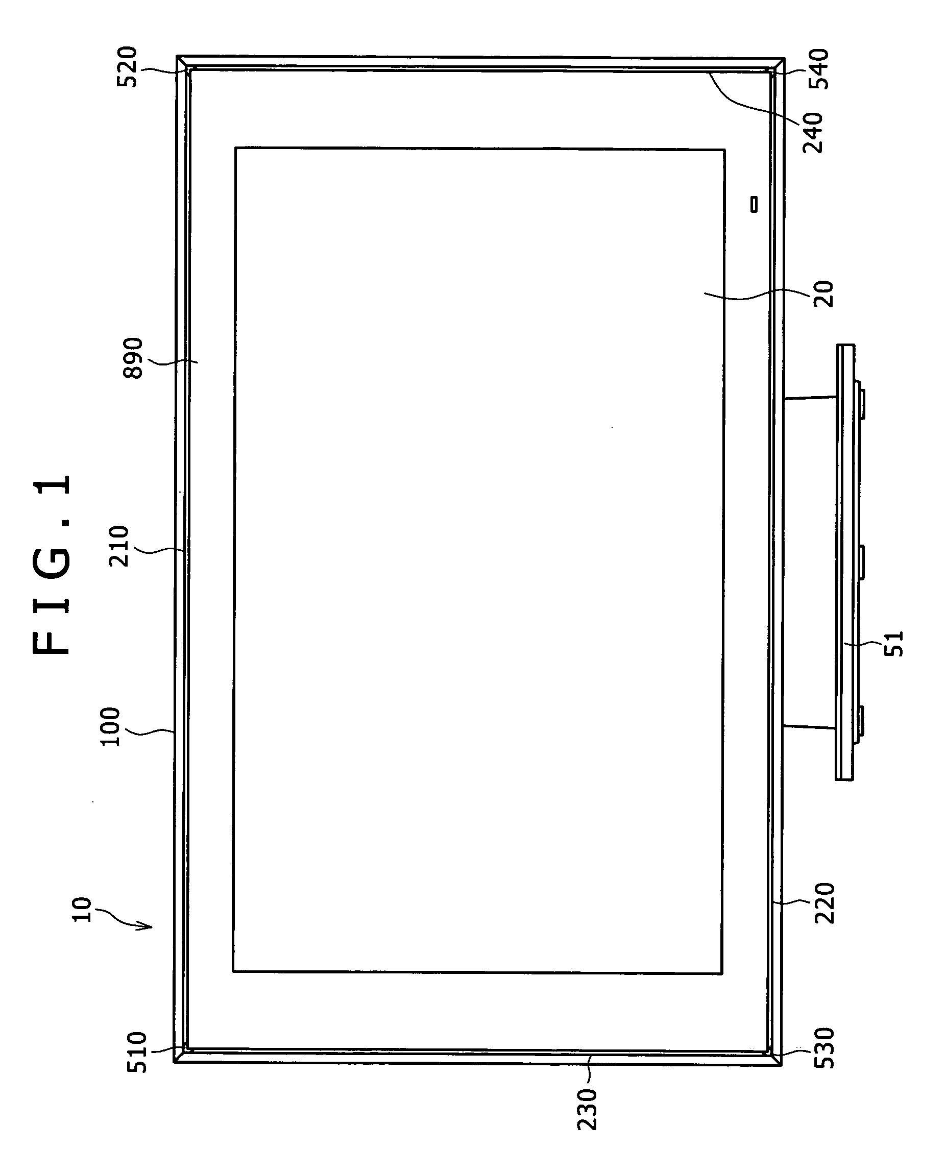
[0030]FIG. 1 shows an electronic device according to the present invention, which incorporates a frame assembly according to the present invention. In FIG. 1, the electronic device includes a liquid crystal display panel device.

[0031] As shown in FIG. 1, the liquid crystal display panel device includes a frame assembly 10 and a liquid crystal display panel 20, and is mounted on a stand 51.

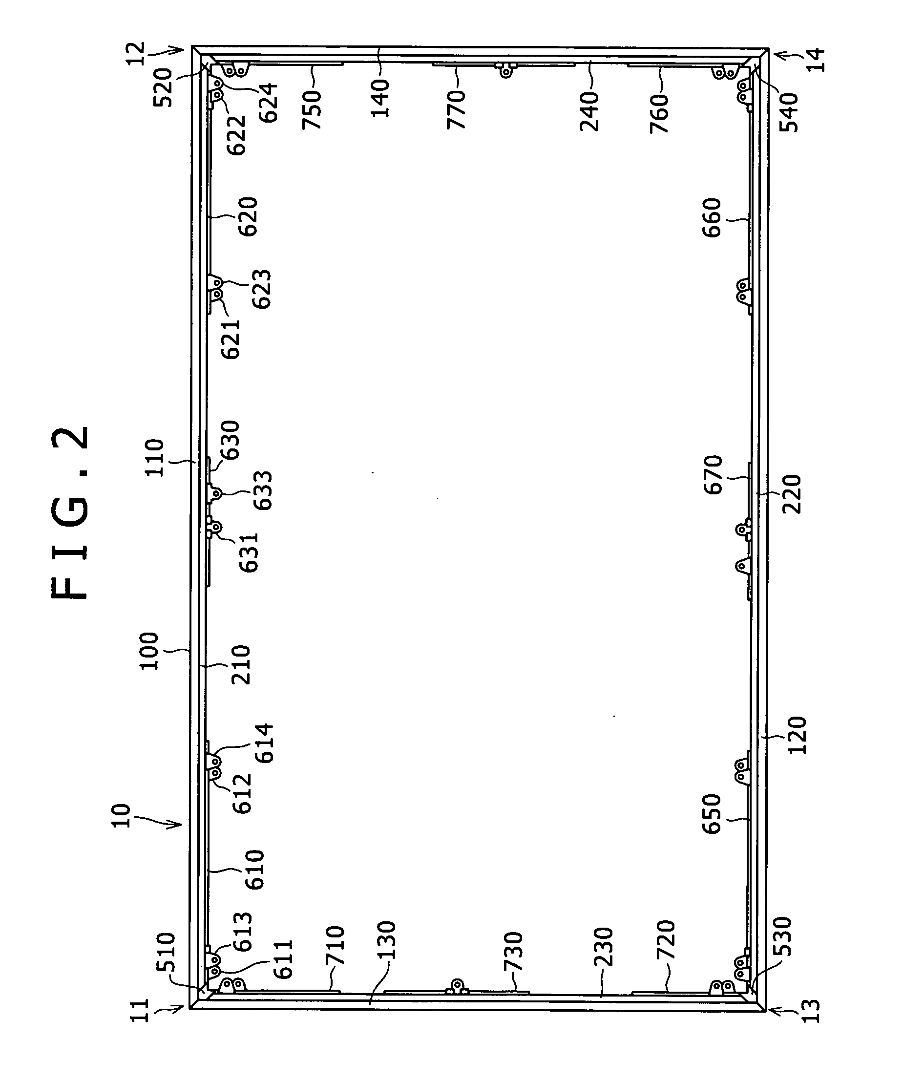
[0032] The frame assembly 10 includes an outer frame 100, an inner frame (cabinet) that is omitted from illustration in FIG. 1, a transparent upper side plate 210, a transparent lower side plate 220, a transparent left side plate 230, and a transparent right side plate 240. The outer frame 100 has upper left, upper right, lower left, and lower right corners combined with respective corner covers 510, 520, 530, 540.

[0033] The transparent upper side plate 210, the transparent lower side plate 220, the transparent left side plate 230, and the transparent right side plate 240 serve to create a float...


PUM


Abstract

An outer frame has an outer frame upper side plate, an outer frame lower side plate, an outer frame left side plate, and an outer frame right side plate. In an upper right corner, a transparent upper side plate, a transparent right side plate, and holders are applied to inner surfaces of the outer frame upper side and the outer frame right side plate, and are held together by a corner joint and a corner bracket that are inserted into a right end of the outer frame upper side plate and the outer frame right side plate. Upper left, lower left, and lower right corners are similarly assembled.

Description

BACKGROUND OF THE INVENTION [0001] The present invention relates to a frame assembly for use as an outer casing or housing of various electronic devices, and an electronic unit having an electronic device such as a flat display panel, e.g., a liquid-crystal display panel, mounted in a frame assembly. [0002] Flat display panels such as liquid-crystal display panels and plasma display panels have frame components attached thereto and are mounted in frame assemblies. [0003] Japanese Patent Laid-open No. 2004-69822 discloses a frame structure including holders mounted on and gripping left and right skirts of a rear frame of a flat display panel and holders mounted on and gripping left and right ends of a front transparent panel of the flat display panel. [0004] Japanese Patent Laid-open No. 2004-61922 discloses a housing mounted on a rear side of a flat display panel and speaker storage regions on left and right ends of a front glass plate of the flat display panel. [0005] There is a de...

Claims


Application Information

Patent Timeline
IPC IPC(8): H05K5/02G02F1/1333G09F9/00
CPCG02F1/133308G02F2201/465G02F2001/133328G02F1/133328H01J11/20
Inventor SHOJI, JUNICHINAGANO, MASAHIRO
Owner SONY CORP
Why Eureka
Try Eureka