
Communication/broadcast multiplexer and demultiplexer used in communication/broadcast-integrated system

a communication/broadcast multiplexer and integrated system technology, applied in the field of passive optical network, can solve the problems of complex media access control (mac) technology, inability to transparently provide data to subscribers, and many limitations in the capacity and speed of prior art to accommodate such data

Inactive Publication Date: 2006-01-26
SAMSUNG ELECTRONICS CO LTD
View PDF7 Cites 32 Cited by
  • Summary
  • Abstract
  • Description
  • Claims
  • Application Information

AI Technical Summary

Problems solved by technology

However, the prior art has many limitations in accommodating such data in terms of its capacity and speed.
Among them, the ATM-PON and Ethernet PON have problems in that they have no transparency about the speed of data to be provided to subscribers.
Further they use an Optical Line Terminal (OLT), which requires complicated Media Access Control (MAC) technologies because it uses the same wavelength in upstream transmission.
The ATM-PON and Ethernet PON also have difficulties in accommodating digital broadcasts.
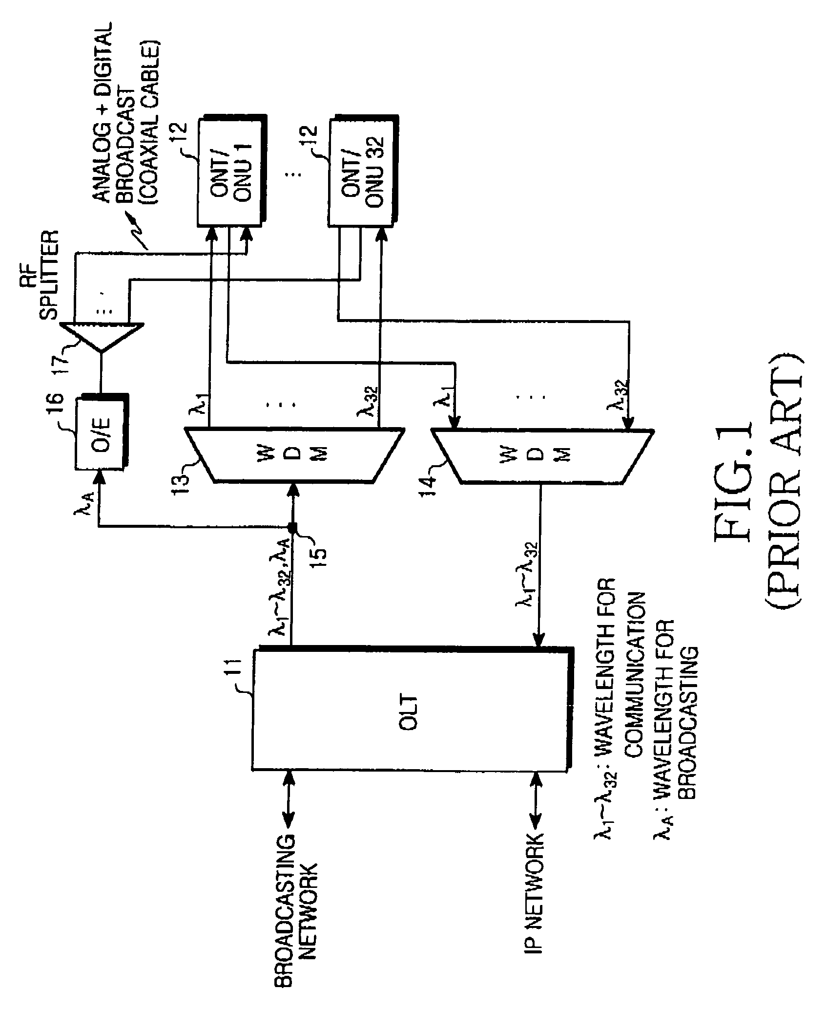
That is, the conventional WDM-PON cannot integrate broadcast and communication signals into a single signal to provide broadcast and communication services.
However, existing cable networks cannot accommodate analog / digital broadcasts.
The conventional WDM-PON of FIG. 1 thus has a problem in that the accommodation of analog / digital broadcasts requires replacement of a lead-in coaxial cable in each subscriber with a coaxial cable of an extended band.
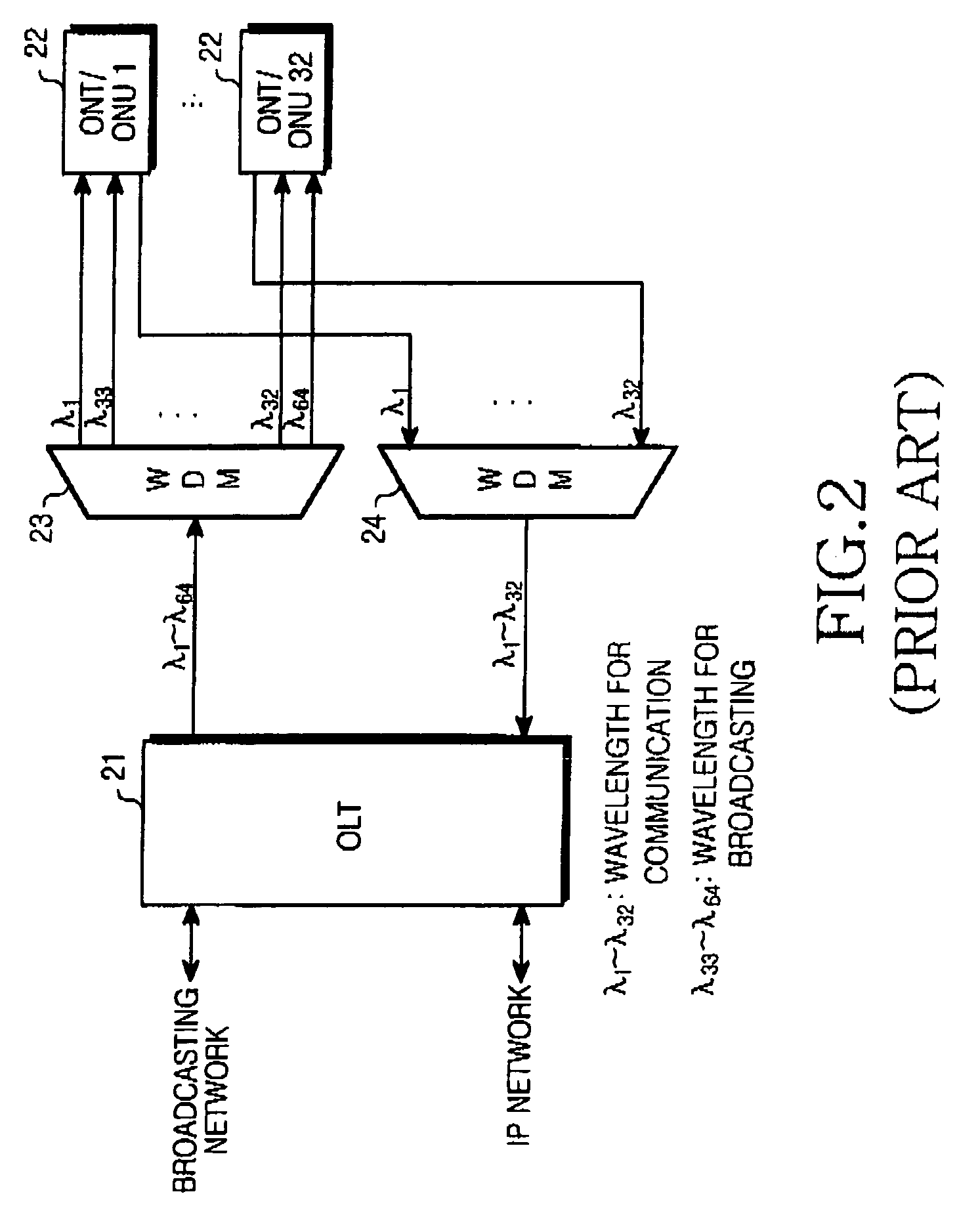
However, as with the prior art of FIG. 1, the WDM-PON of FIG. 2 does not suggest a technology for integrating and transmitting broadcast and communication signals.
This increases the cost of the WDM-PON system, imposing a burden on the subscribers.

Method used


Image

  • Communication/broadcast multiplexer and demultiplexer used in communication/broadcast-integrated system
  • Communication/broadcast multiplexer and demultiplexer used in communication/broadcast-integrated system
  • Communication/broadcast multiplexer and demultiplexer used in communication/broadcast-integrated system

Examples


first embodiment

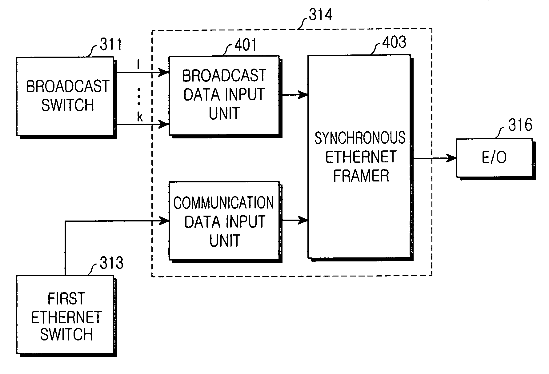
[0061]FIGS. 4a and 4b are block diagrams illustrating the respective configurations of a communication / broadcast multiplexer and a communication / broadcast demultiplexer according to the present invention.

[0062] The communication / broadcast multiplexer according to the first embodiment uses synchronous Ethernet for communication / broadcast multiplexing.

[0063]FIG. 5 illustrates a data structure for synchronous Ethernet. As shown in FIG. 5, synchronous Ethernet data includes an asynchronous data frame 502 and a plurality of synchronous data frames 501. According to the synchronous Ethernet, when conventional communication data including Ethernet data and control data is transmitted together with data (for example, multimedia data such as MPEG-TS) requiring real-time processing, the data requiring real-time processing is transmitted synchronously with a predetermined cycle, thereby minimizing the delay of the data requiring real-time processing. The synchronous Ethernet satisfies IEEE 80...

second embodiment

[0067]FIGS. 6a and 6b are block diagrams illustrating the respective configurations of a communication / broadcast multiplexer and a communication / broadcast demultiplexer according to the present invention.

[0068] The communication / broadcast multiplexer according to the second embodiment uses an Ethernet MAC framer for communication / broadcast multiplexing.

[0069] As shown in FIG. 6a, the communication / broadcast multiplexer 314 according to the second embodiment includes an Ethernet MAC framer 601, an Ethernet MAC switch 602, and an output physical unit 603. The communication / broadcast multiplexer 314 incorporates broadcast signals into an Ethernet MAC frame in the following manner. The Ethernet MAC framer 601 in the communication / broadcast multiplexer 314 receives MPEG-TS signals switched on a subscriber basis through a broadcast switch 311. It allocates source and destination addresses to each of the MPEG-TS signals, and then incorporates the MPEG-TS signals into an Ethernet MAC frame...

third embodiment

[0075]FIGS. 7a and 7b are block diagrams illustrating the respective configurations of a communication / broadcast multiplexer and a communication / broadcast demultiplexer according to the present invention.

[0076] The communication / broadcast multiplexer according to the third embodiment uses IEEE 1394 transmission for communication / broadcast multiplexing.

[0077] IEEE 1394a, which is one version of the IEEE 1394 used in the embodiments of the present invention, theoretically supports up to 400 Mbps. IEEE 1394b, which is another version thereof, theoretically supports up to 3.2 Gbps, and is backwards compatible.

[0078]FIG. 8 illustrates a data structure for IEEE 1394 transmission. As shown in FIG. 8, an IEEE 1394 frame has a cycle of 125 μs, and supports two data formats. The first is an isochronous data format 802 suitable for transmission of a broadcast MPEG-TS and the second is an asynchronous data format 803 suitable for transmission of communication data and control signals. To acco...


PUM


Abstract

A communication / broadcast multiplexer and demultiplexer for multiplexing and demultiplexing communication and broadcast signals using a specific transmission standard in an optical network system that integrates broadcast and communication services using a channel selection technique. The multiplexer comprises a broadcast data input unit, a communication data input unit, and a synchronous Ethernet framer. The broadcast data input unit receives broadcast data switched on a subscriber basis through a broadcast switch in an optical line terminal (OLT) in the system, and transfers it as a synchronous data frame to the synchronous Ethernet framer. The communication data input unit receives communication data on a subscriber basis through an Ethernet switch in the OLT and transfers it as an asynchronous data frame to the synchronous Ethernet framer. The synchronous Ethernet framer converts both the received synchronous and asynchronous data frames into a TDM synchronous Ethernet frame, and outputs the TDM synchronous Ethernet frame.

Description

CLAIM OF PRIORITY [0001] This application claims priority to an application entitled “COMMUNICATION / BROADCAST MULTIPLEXER AND DEMULTIPLEXER USED IN COMMUNICATION / BROADCAST-INTEGRATED SYSTEM,” filed in the Korean Intellectual Property Office on Jul. 22, 2004 and assigned Serial No. 2004-57281, the contents of which are incorporated herein by reference. BACKGROUND OF THE INVENTION [0002] 1. Field of the Invention [0003] The present invention relates to a Passive Optical Network (PON) using Wavelength Division Multiplexing (WDM). [0004] 2. Description of the Related Art [0005] Many broadcast and communication service subscribers currently use data communication services such as Internet. Typically the data rates for such services are several tens of Kbps (bits per second) to several tens of Mbps through xDSL, a cable modem, a dial-up modem, metro-Ethernet, etc. They also use broadcasting services such as cable broadcasting through a coaxial cable, satellite broadcasting through a satel...

Claims


Application Information

Patent Timeline
IPC IPC(8): H04J3/26H04J3/16H04J14/02H04L12/44H04Q11/00
CPCH04H20/69H04J14/0226H04J14/0282H04L12/2801H04J14/0252H04Q11/0067H04Q2011/0016H04J14/0232H04J14/0247H04N21/43632
Inventor CHO, JAE-HUNOH, YUN-JEKOH, JUN-HOLEE, KI-CHEOL
Owner SAMSUNG ELECTRONICS CO LTD
Learn More