Light therapy device heat management

Inactive Publication Date: 2006-01-26
MULDNER JAMES SCOTT
View PDF6 Cites 29 Cited by
  • Summary
  • Abstract
  • Description
  • Claims
  • Application Information

AI Technical Summary

Benefits of technology

[0013] 1. Higher light intensity, to a given area thus reducing treatment time, by using metal core circuit board heat

Problems solved by technology

Pecukonis6, in U.S. Pat. No. 6,471,716 (Jun. 11, 2002), addresses living tissue therapy in the infrared light spectrum and does not address problems concerning LED array replacement or h

Method used


Image

  • Light therapy device heat management
  • Light therapy device heat management
  • Light therapy device heat management

Examples


Embodiment Construction

[0033] Detailed descriptions of the preferred embodiment are provided herein. It is to be understood, however, that the present invention may be embodied in various forms. Therefore, specific details disclosed herein are not to be interpreted as limiting, but rather as a basis for the claims and as a representative basis for teaching one skilled in the art to employ the present invention in virtually any appropriately detailed system, structure, or manner.

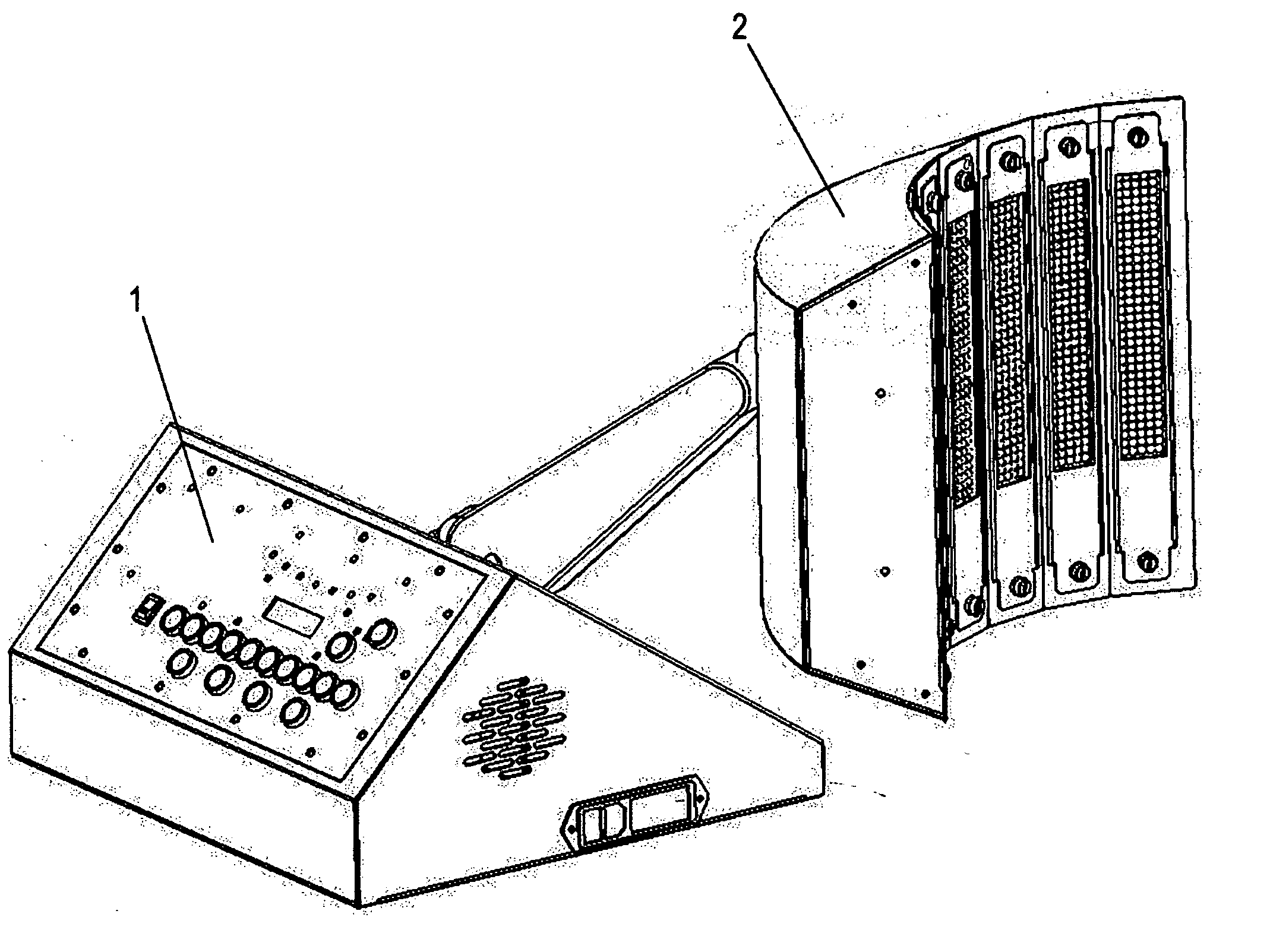
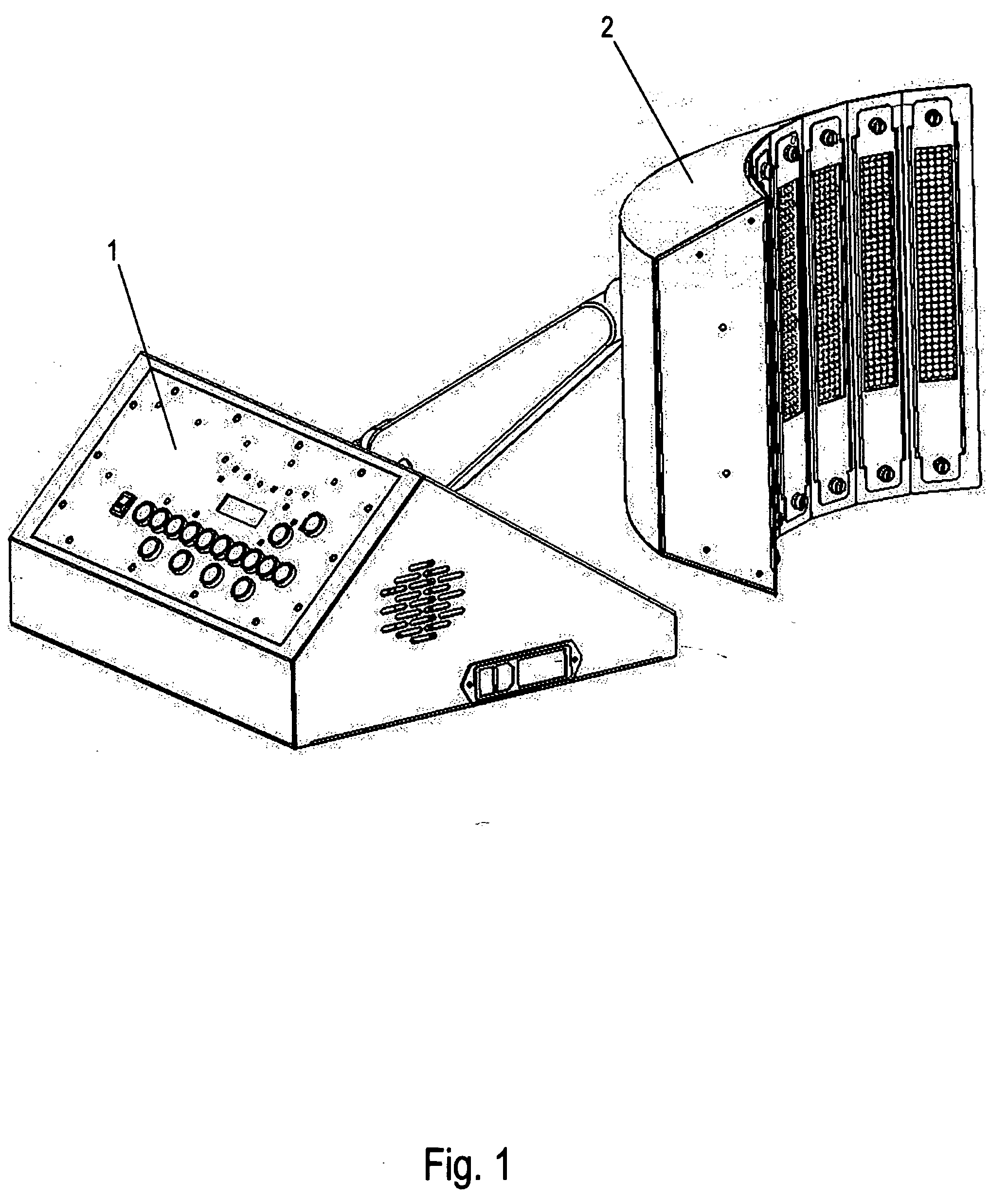
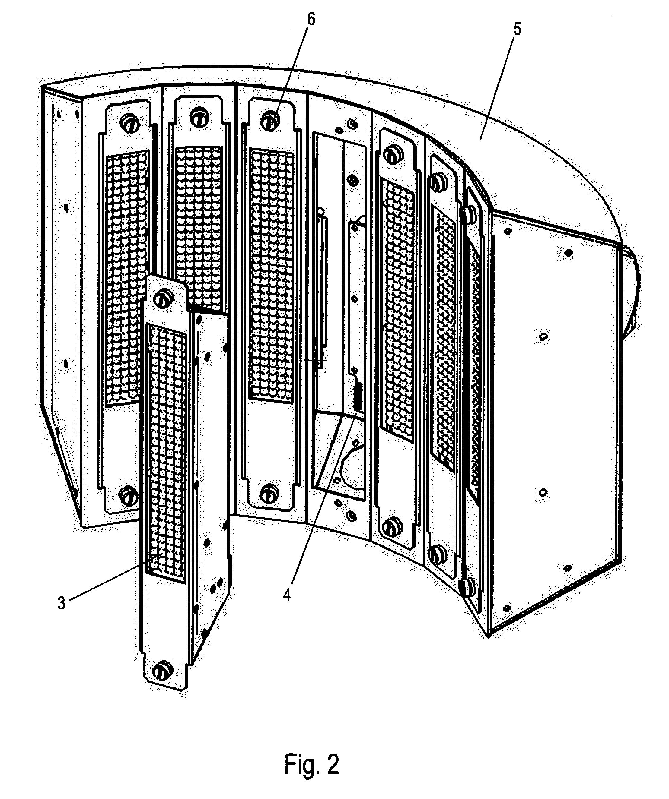
[0034] Turning to FIG. 1, one sees a perspective view of a version of the completed light therapy device including a operator control panel (1) and the light therapy device (2) incorporating the present invention. In accordance with an important feature of the present invention, FIG. 2 shows a version of the light therapy device containing the operator removable LED array module (3), and the power transfer connector (4) for attaching the LED array module (3) to the shroud (5). The mounting screws (6) are used to mount or dismount ...


PUM


Abstract

This device incorporates an array of light emitting diodes (LED) of several specific wavelengths that are used to provide therapy to visible and invisible living tissue or skin disorders that react to various wavelengths of light. Furthermore the device uses a combination of high level of perforation metal core circuit boards, heat transfer pads, heat sinks and forced air cooling and electronic thermal management to achieve continuous high intensity light output to therapy areas along with long LED life. The invention is using replaceable LED modules enabling device maintenance by user operators not trained as maintenance technicians.

Description

CROSS REFERENCE TO RELATED APPLICATIONS [0001] Not Applicable STATEMENT REGARDING FEDERALLY SPONSORED RESEARCH OR DEVELOPMENT [0002] Not Applicable DESCRIPTION OF ATTACHED APPENDIX [0003] Not Applicable BACKGROUND OF THE INVENTION [0004] 1. Field of Invention [0005] This invention relates generally to the field of medical living tissue using light therapy in and more specifically to improvement of light devices used in therapy of visible and invisible skin disorders that react to various wavelengths of light. [0006] 2. Prior Art [0007] Diamantopolus1, et al. in U.S. Pat. No. 4,930,504 (Jun. 5, 1990) and other references teach us that certain wavelengths of light ranging from 600 nm thru 1500 nm are effective in biostimulation of tissue. For many years, high-powered highly focused lasers have been used to cut and destroy tissues in many surgical techniques. More recently, low powered lasers, less sharply focused, which do not cut or destroy tissues have been found to, or thought to, ...

Claims


Application Information

Patent Timeline
IPC IPC(8): A61N5/06
CPCA61N5/0616A61N2005/005A61N2005/0662A61N2005/0652A61N2005/0659A61N2005/0642
Inventor MULDNER, JAMES SCOTT
Owner MULDNER JAMES SCOTT
Why Eureka
Try Eureka