
Method and surveillance system for surveilling the state of work machines

a surveillance system and work machine technology, applied in the direction of electric testing/monitoring, instruments, mechanical means, etc., to achieve the effect of improving the quality and automatizing the effect of the surveillance system

Inactive Publication Date: 2006-01-26
DEERE & CO
View PDF10 Cites 36 Cited by
  • Summary
  • Abstract
  • Description
  • Claims
  • Application Information

AI Technical Summary

Benefits of technology

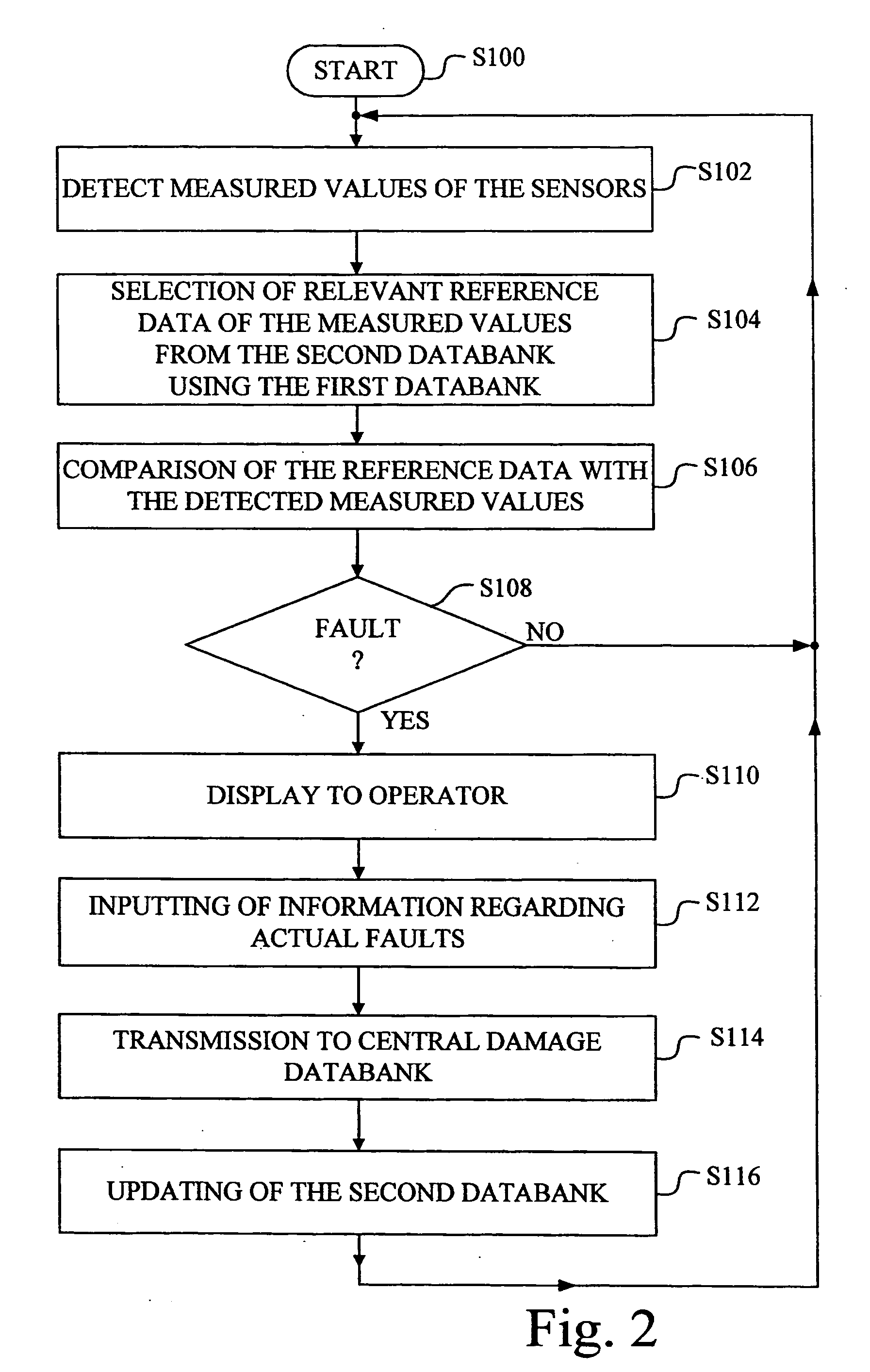
[0011] In this manner a central damage databank is gradually built up that is based on actual instances of damage. The second databank, used for the analysis of the measured values, is updated based on these instances of damage. It therefore becomes more and more reliable. The constant updating of the second databank expands the diagnosis to more and more construction elements and refines the localizing of the faults more and more. This constantly improves the quality and the automatization effect of the surveillance system. The great number of work machines being used and the different instances of use and of stress that occur make it possible for a comprehensive, statistically reliable collection of experiences to be rapidly compiled. This collection can be used to rapidly obtain an intelligent surveillance system.

Problems solved by technology

There is therefore the possibility that after a repair has been made of re subjecting the measured values of the sensors to an analysis of faults of the machine.

Method used


Image

  • Method and surveillance system for surveilling the state of work machines
  • Method and surveillance system for surveilling the state of work machines
  • Method and surveillance system for surveilling the state of work machines

Examples


Embodiment Construction

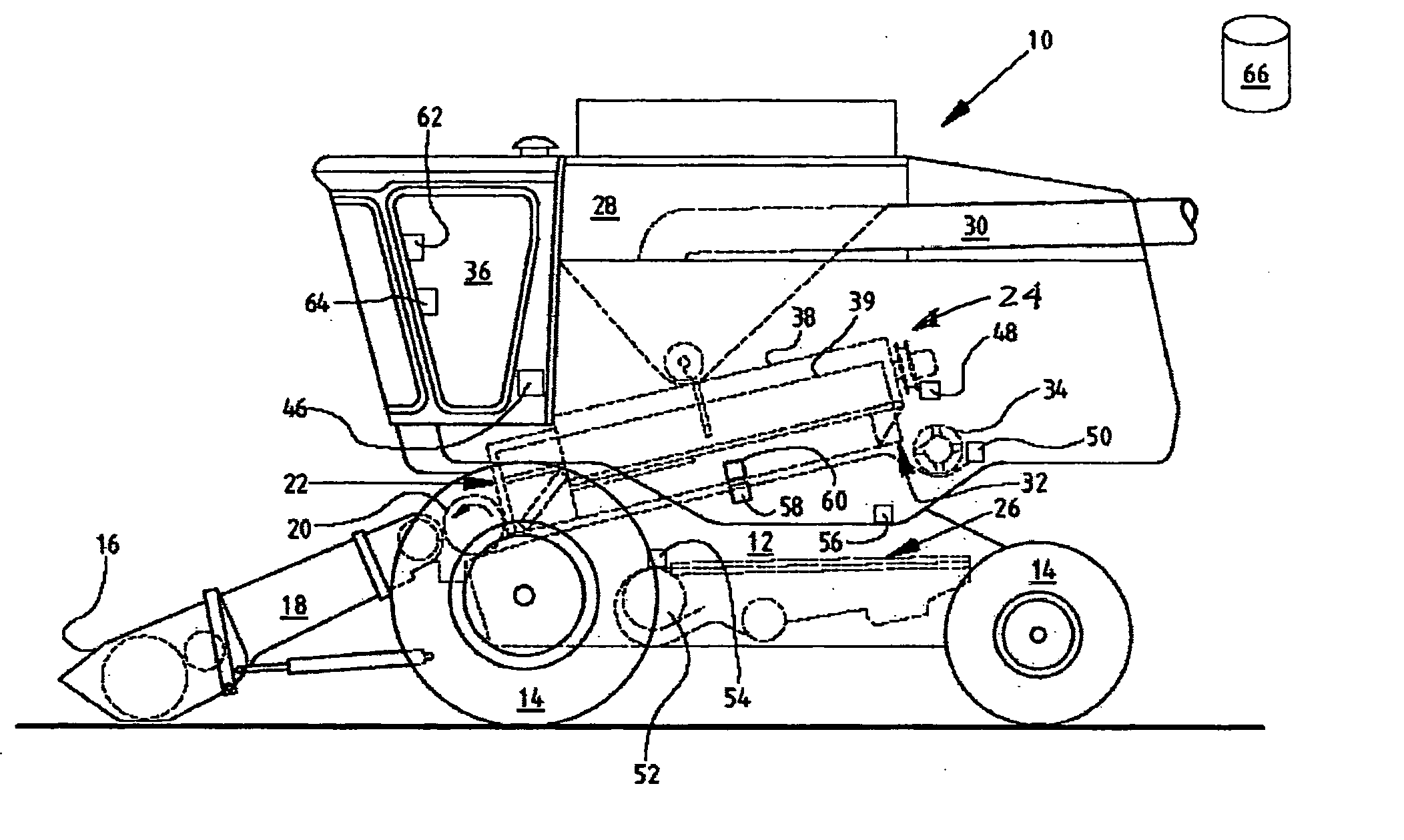
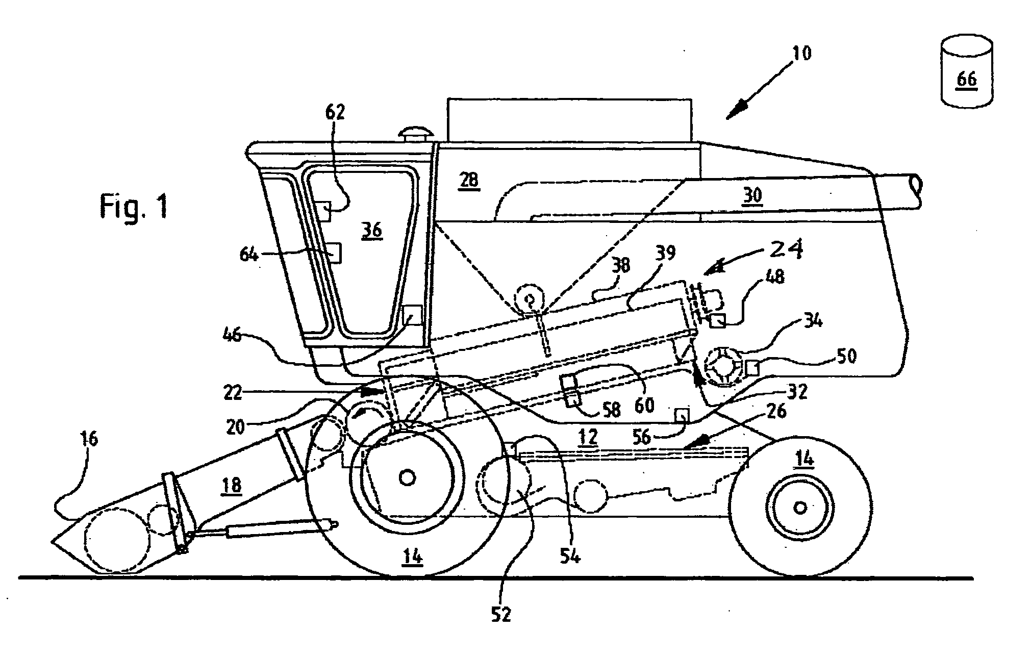
[0018] Referring now to the drawings, and more particularly to FIG. 1, there is shown an agricultural combine 10 with a frame 12 and ground wheels 14 extending down from frame 12. The invention will be explained using combine 10 as an example. Crop harvesting device 16, in the form of a cutting unit, is used to gather a crop and feed it to oblique conveyor 18. The crop is fed by oblique conveyor 18 to guide drum 20. Guide drum 20 conducts the crop upward through inlet transition area 22 to axial separating device 24.

[0019] Axial separating device 24 threshes and separates the harvested crop. Grain and chaff fall through grates on the bottom of axial separating device 24 into cleaning system 26. Cleaning system 26 removes the chaff and feeds the clean grain to a grain elevator (not shown). The grain elevator deposits the clean grain in grain tank 28. The clean grain in grain tank 28 can be unloaded by unloading worm 30 into a trailer or truck. Threshed straw freed of grain is conduc...


PUM


Abstract

A method and a surveillance system for surveilling the state of work machines including the steps of the making available sensors for detecting the operating state of the work machines; the making available of a first work machine specific databank with construction data; the making available of a second work machine specific databank with evaluation specific reference data; and analyzing of the measured values of the sensors regarding possible faults of a work machine using the first and the second databank. If the analysis of the measured values indicates a fault in the work machine, then a presentation of information to an operator is accomplished regarding the presence of a possible fault and the determined fault location. Inputs of the operator are received regarding faults that are found by him. The measured values and / or of analyzed results derived from them and of operator inputs are transmitted to a central damage databank and the central damage databank is updated. The second databank is updated based on the updated damage databank.

Description

FIELD OF THE INVENTION [0001] The invention relates to a method and a surveillance system for surveilling the state of work machines. BACKGROUND OF THE INVENTION [0002] German Patent DE 101 00 522 A describes a surveillance device for a work machine. It includes one or more sensors that detect noises made by moving elements of the work machine. The signals of the sensors are compared with reference values in order to find out whether the work machine is working properly or whether there is a fault requiring a repair. The reference values stem from free work machines and are received in an investigated work machine or in corresponding work machines with a known fault. [0003] German Patent DE 199 38 722 A describes a method of analyzing roller bearings in machines. A sensor receives a signal produced by the rolling off movement of roller bearings. The amplitude of the signal is evaluated in order to determine the presence and, optionally, the depth of damage in a roller bearing runnin...

Claims


Application Information

Patent Timeline
Patent Type & Authority Applications(United States)
IPC IPC(8): G01B3/44A01D41/127G01H1/00G05B23/02G07C3/00G07C5/00G07C5/08
CPCA01D41/127G01H1/00G07C5/085G07C3/00G07C5/008G01H1/003
Inventor BISCHOFF, LUTZBECK, FOLKERBRAUNHARDT, KLAUSHERLITZIUS, THOMAS
Owner DEERE & CO
Learn More