Automatic analog test & compensation with built-in pattern generator & analyzer

an analog and pattern generator technology, applied in the field can solve the problems of mixed signal systems, and high-speed radio frequency integrated circuits, and achieve the effects of reducing the cost of analog functionality testing

Active Publication Date: 2006-01-26
AUBURN UNIV
View PDF6 Cites 28 Cited by
  • Summary
  • Abstract
  • Description
  • Claims
  • Application Information

AI Technical Summary

Problems solved by technology

Analog functionality testing in mixed signal systems and high-speed radio frequency integrated circuits (RFIC) is a time-consuming and costly process based on the current methodology of manual analog testing.
Typical test costs, as a percentage of the manufacturing cost, can be as high as 50% of the total cost, depending on the complexity of the functionality to be tested.
The overall cost of an RF system consists of manufacturing, testing (wafer sort and final testing) and packaging.
Typically, the RF circuitry is bypassed due to the high cost of RF testers.
Unfortunately, RF packaging can represent 30% of the overall cost.
Current test practices are expensive because of, among other reasons, the required tester infrastructure, long test times, cumbersome test preparation, lack of appropriate defect and fault models, and lack of standardized test methods.
These approaches normally focus on one or two simple parameter tests such as cut-off frequency of a filter and cannot perform rigorous and complete analog tests such as frequency response, linearity, noise and modulation tests.
These approaches are simple, but their precision is limited.
The precision of the generated frequency is not fine enough to support some analog tests such as various analog modulation and linearity test using precise two-tones.

Method used


Image

  • Automatic analog test & compensation with built-in pattern generator & analyzer
  • Automatic analog test & compensation with built-in pattern generator & analyzer
  • Automatic analog test & compensation with built-in pattern generator & analyzer

Examples


Embodiment Construction

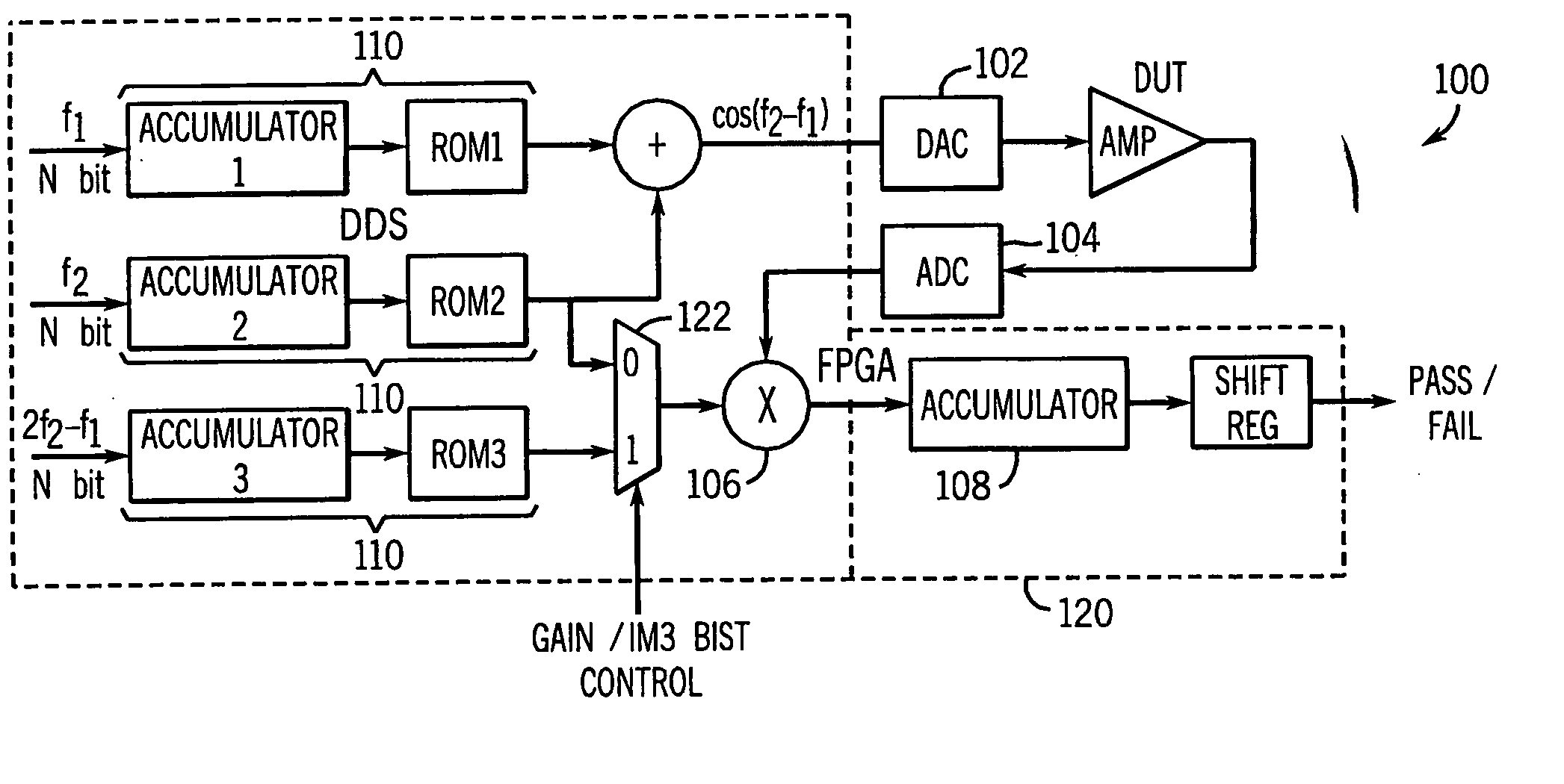
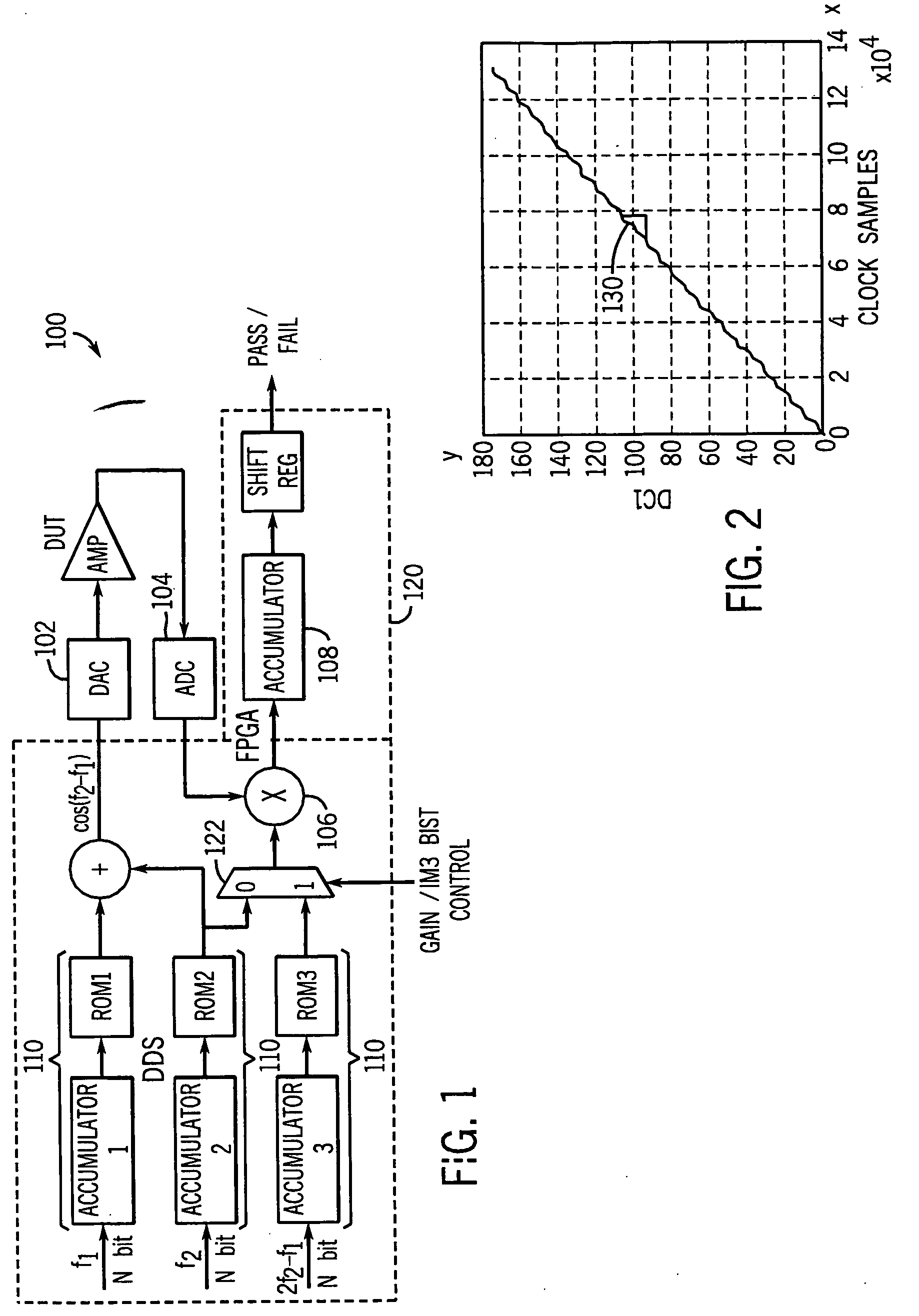
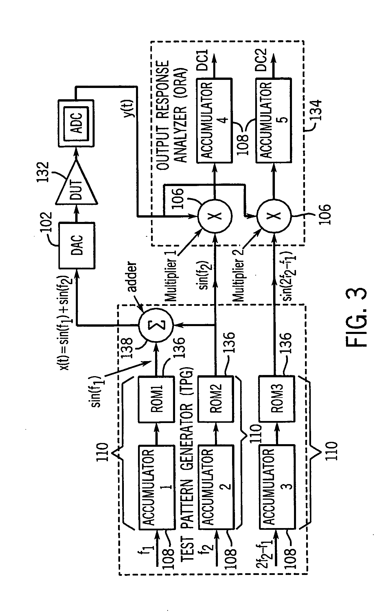
[0021] A DDS 110 based BIST architecture 100, which can generate various modulated waveforms and frequency tones for analog functionality test is described herein. A schematic diagram illustrating this BIST architecture 100 is illustrated in FIG. 1. This DDS 110 based BIST architecture 100 detects faults and assists in characterization and calibration during manufacturing and field testing. Embodiments for base-band digital test features such as the test pattern generator (TPG) and output response analyzer (ORA) 134, the functionality is synthesized in Field Programmable Gate Array (FPGA) 120 circuitry, while other embodiments fabricate the design in a CMOS application specific integrated circuit (ASIC). Preferably, in operation the vast majority of the BIST circuitry 100 resides in the digital portion of the subject mixed-signal system being tested to minimize performance impact on the analog circuitry. The only test circuitry added to the analog domain of the system being tested a...


PUM


Abstract

A built-in-self test (BIST) scheme for analog circuitry functionality tests such as frequency response, gain, cut-off frequency, signal-to-noise ratio, and linearity measurement. The BIST scheme utilizes a built-in direct digital synthesizer (DDS) as the test pattern generator that can generate various test waveforms such as chirp, ramp, step frequency, two-tone frequencies, sweep frequencies, MSK, phase modulation, amplitude modulation, QAM and other hybrid modulations. The BIST scheme utilizes a multiplier followed by an accumulator as the output response analyzer (ORA). The multiplier extracts the spectrum information at the desired frequency without using Fast Fourier Transform (FFT) and the accumulator picks up the DC component by averaging the multiplier output.

Description

CROSS REFERENCE TO RELATED APPLICATION(S) [0001] The present Application is based on and claims priority under 35 U.S.C. §119(e) of the co-pending U.S. Provisional Patent Application, Ser. No. 60 / 590,200, filed Jul. 22, 2004, and entitled “AUTOMATIC ANALOG TEST & COMPENSATION WITH BUILT-IN PATTERN GENERATOR & ANALYZER”. The U.S. Provisional Patent Application, Ser. No. 60 / 590,200, filed Jul. 22, 2004, and entitled “AUTOMATIC ANALOG TEST & COMPENSATION WITH BUILT-IN PATTERN GENERATOR & ANALYZER” is also hereby incorporated by reference. [0002] The present Application is based on and claims priority under 35 U.S.C. §119(e) of the co-pending U.S. Provisional Patent Application, Ser. No. 60 / 652,410, filed Feb. 11, 2005, and entitled “AUTOMATIC ANALOG TEST & COMPENSATION WITH BUILT-IN PATTERN GENERATOR & ANALYZER”. The U.S. Provisional Patent Application, Ser. No. 60 / 652,410, filed Feb. 11, 2005, and entitled “AUTOMATIC ANALOG TEST & COMPENSATION WITH BUILT-IN PATTERN GENERATOR & ANALYZE...

Claims


Application Information

Patent Timeline
Patent Type & Authority Applications(United States)
IPC IPC(8): G06F11/00
CPCG01R31/31813G01R31/3167
Inventor DAI, FASTROUD, CHARLES E.
Owner AUBURN UNIV
Why Eureka
Try Eureka